2
3
A
B
C
D
E
F
G
H
I
K
L
M
N
O
P
Q
R
S
T
U
V
W
X
______ END ______
| Term: 2D |  |
| Definition: Two-dimensional space |
| Term: 2D CAD | |
| Definition: The digital file produced from any CAD software package that creates a 2D drawing, which is the source for either printed-paper or a digital 2D formatted file (e.g., PDF). These files may or may not retain an associative link to their 3D CAD parent. |
| Term: 2D Data | |
| Definition: Technical information presented as a 2D drawing or other static document types that require manual human interpretation. |
| Term: 2D TDP | 2-Dimensional Technical Data Package |
|
| Definition: A 2-Dimensional Technical Data Package is based on 2 dimensional engineering drawings in accordance with ASME Y14.100 series standards. |
| Term: 3-Dimensional Intelligent Technical Data | 3Di |
|
| Definition: A 3-dimensional viewable representation of an item provided in a widely available software format (e.g. ISO 32000-1 Portable Document Format (PDF)). This representation details the complete technical description of the required design configuration to include but not limited to geometry, topology, relationships, tolerances, attributes, metadata and other features necessary to define a component or assembly. |
| Term: 3D | |
| Definition: Three-dimensional space |
| Term: 3D CAD | |
| Definition: The digital file(s) produced from any CAD software package that contains the 3D model of an object. It may or may not include Product and Manufacturing Information (PMI) annotations. | 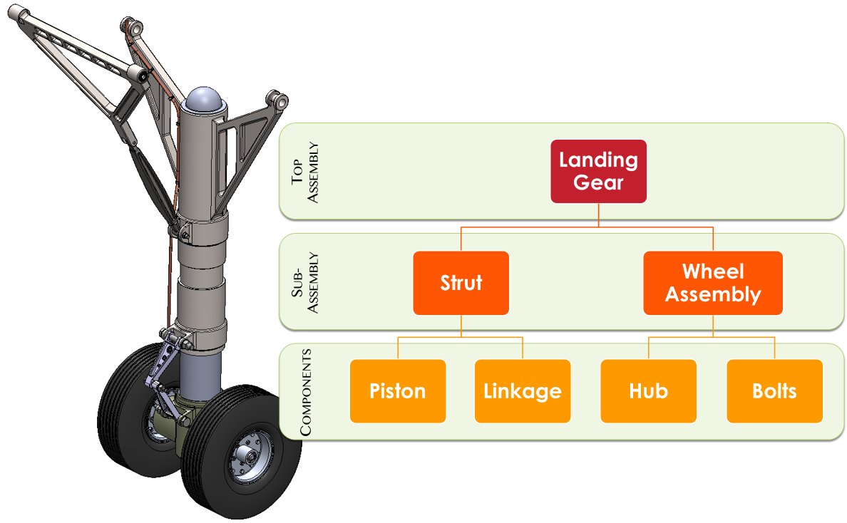 |
| Term: 3D CAD Model | |
| Definition: 3D Model of a physical item that is generated using drafting and design software. |
| Term: 3D Data | |
| Definition: Technical information presented as a dynamic 3D model that facilitates machine consumption opportunities while also displaying much of the 3D data for the human reviewer. |
| Term: 3D Drawing | |
| Definition: A term often used to describe a 3D PDF. It is a mathematically inaccurate term because a drawing is inherently 2D, and should not be described as 3D. |
| Term: 3D Interactive Viewable | 3DIV |
|
| Definition: A three-dimensional derivative model that is interactive and is published in a ubiquitous format. | 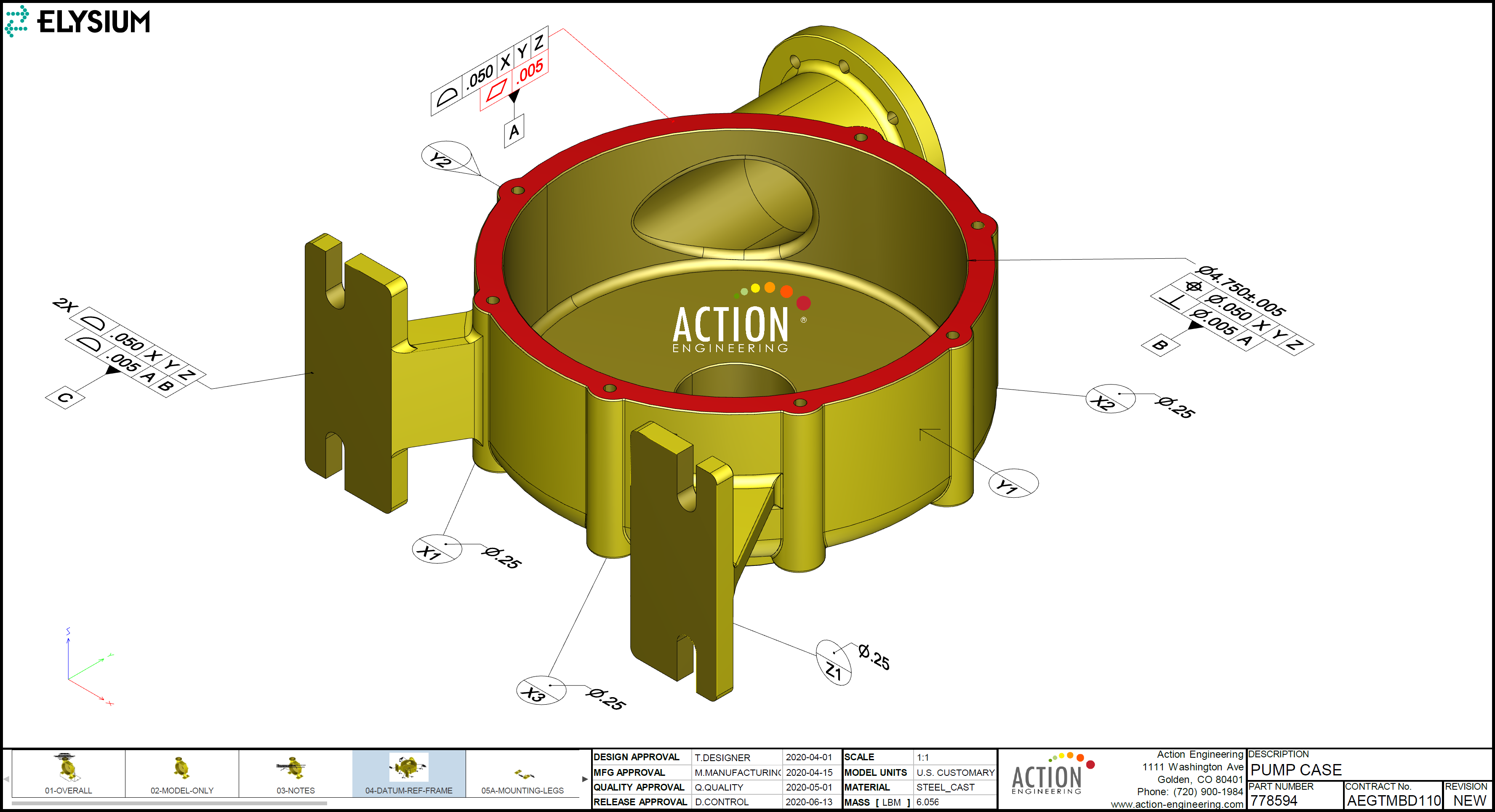 |
| Term: 3D Interoperability | |
| Definition: The capability of 3D data to seamlessly interchange between disparate systems. |  |
| Term: 3D Model | |
| Definition: A three-dimensional spatial model. |
| Term: 3D Model Based Definition | 3D MBD |
|
| Definition: Model Based Definition (MBD) is a set of concepts, processes, and tools that allow the creation of an annotated 3D product definition based on a 3D solid model. The MBD dataset includes all Engineering Intent requirements (including Process Specifications, Geometric Dimensioning & Tolerancing (GD&T), and other required information). Combined with product lifecycle management (PLM) attributes, a parts list, and general notes, this constitutes an authoritative, single source of master product definition data that does not include or depend upon traditional 2D drawings. The MBD dataset defines complete requirements for a product in its nominal condition as well as permissible limits of variation and other acceptance criteria, providing all the data needed to plan, fabricate, and validate an article of product hardware. |
| Term: 3D PDF | |
| Definition: A PDF file that contains 3D geometry with associated text in a dynamic viewport. |
| Term: 3D Printer | |
| Definition: A machine used for additive manufacturing. |
| Term: 3D Scanning | |
| Definition: A method of digitally acquiring and storing the shape and size of an object as a 3D data. |
| Term: 3D TDP | 3-Dimensional Technical Data Package |
|
| Definition: A 3-Dimensional Technical Data Package is based on product model data that is capable of generating derivative products including but not limited to 2D TDP, 3D lightweight graphical representations, and neutral data formats. |
| Term: 3Di format | |
| Definition: The standard arrangement and organization of information within a 3Di viewable representation of an item. This includes such features as the size and arrangement of information blocks (e.g. title blocks), notes, lists, revision information, view states, restriction notices and the use of optional or supplemental blocks (see related term Drawing Format). |
| Term: Actual Component | |
|
Definition: a physical instance of a component
Note 1 to entry: By analogy to a car, the design of a wheel is a part; the design of the wheel placed at the front right of the design of a car is a component; the front right wheel of a physical car is an actual component. |
| Term: Actual Local Size | |
| Definition: The actual value of any individual distance at any cross section of a feature of size. |
| Term: Actual Mating Envelope | AME |
|
| Definition: A similar perfect feature(s) counterpart of smallest size that can be contracted about an external feature(s) or of largest size that can be expanded within an internal feature(s) so that it coincides with the surface(s) at the highest points. This envelope is on or outside the material. There are two types of AMEs, as described below. (a) related AME: a similar perfect feature(s) counterpart expanded within an internal feature(s) or contracted about an external feature(s) while constrained in orientation, in location, or in both orientation and location to the applicable datum(s). (b) unrelated AME: a similar perfectfeature(s) counterpart expanded within an internal feature(s) or contracted about an external feature(s), and not constrained to any datum(s). |
| Definition: A similar perfect feature(s) counterpart of largest size that can be expanded within an external feature(s) or of smallest size that can be contracted about an internal feature(s) so that it coincides with the surface(s) at the lowest points. This envelope is on or within the material. There are two types of actual minimum material envelopes, as described below. (a) related actual minimum material envelope: a similar perfect feature(s) counterpart contracted about an internal feature(s) or expanded within an external feature(s) while constrained in orientation, in location, or in both orientation and location to the applicable datum(s). (b) unrelated actual minimum material envelope: a similar perfect feature(s) counterpart contracted about an internal feature(s) or expanded within an external feature(s), and not constrained to any datum reference frame. |
| Term: Additive Manufacturing | AM |
|
| Definition: A process of joining materials to make objects from 3D data, usually layer upon layer, as opposed to subtractive manufacturing methodologies. | 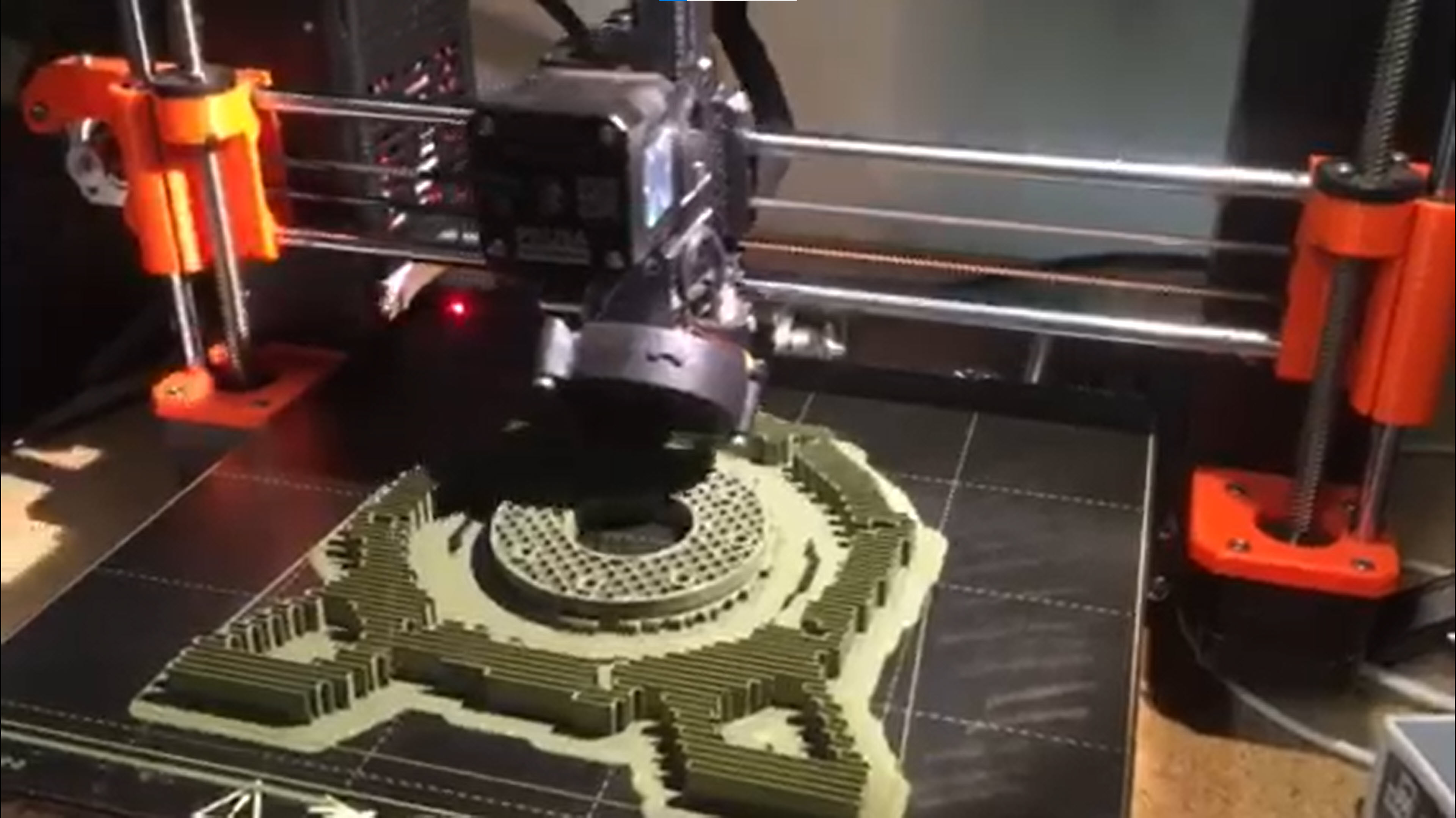 |
| Definition: Any process of additive manufacturing (AM), such as those defined by ISO/ASTM 52900. |
| Definition: A number assigned to one or more interchangeable purchased items for administrative purposes. It also serves as the part or identifying number (PIN) for specifying such items in a parts list. An administrative control number may be assigned by a vendor item control drawing (VICD) or to an item defined by an envelope drawing. The administrative control number is assigned in addition to the item identification assigned by the original design activity. |
| Term: Altered Item Drawing | |
| Definition: A product definition data depicting the alteration of a nationally recognized standard or an item under the control of another design activity where the altered item meets specific design requirements and is no longer interchangeable with the original item. The altered item is re-identified with a new part number from the authoring design activity replacing the original part number. |
| Term: Analysis Model | |
| Definition: A CAD model that contains additional product definition information required to perform product analysis (static, dynamic, thermal, etc.). Most likely contains mesh elements to make it a Finite Element Model (FEM) and may contain control software to predict the products behavior. This may or may not be a derivative of the parent 3D CAD model. |
| Term: Analytical Framework | |
| Definition: A structured and logical approach that serves as a foundation and starting point for conducting data analysis. |
| Term: Angularity | |
| Definition: The condition of a line element, surface, feature's center plane, tangent plane, or feature's axis at an implied or specified basic angle of any value from one or more datum planes or datum axes. |
| Term: Annotated Model | |
| Definition: A combination of model, annotation, and attributes that describe a product. |
| Term: Annotation | |
| Definition: Visible dimensions, tolerances, notes, text, or symbols. | 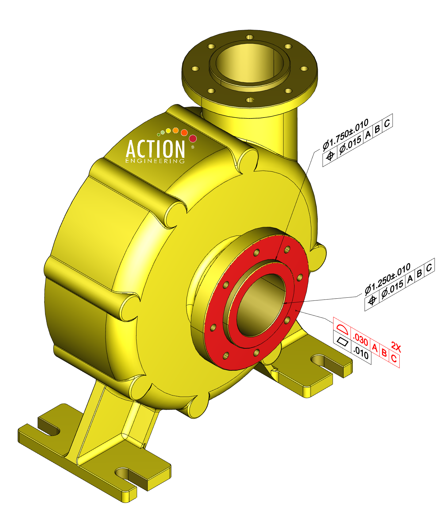 |
| Term: Annotation Element | |
| Definition: An entity in the CAD model that contains an annotation, such as a dimension or a geometric tolerance. |
| Term: Annotation Orientation | |
| Definition: An annotation orientation refers to the plane or the parallel plane in which the annotation lies, the viewing direction and the right direction or text rotation. One should maintain text orientation in a view that provides consistency for viewing. The orientation of the annotation plane should be maintained relative to the model geometry as the model is manipulated in 3D to comply with ASME Y14.41 section 5.2.3. |
| Term: Annotation Plane | |
| Definition: A conceptual plane containing annotation. |
| Definition: The completeness level of the annotations and attributes of an annotated model that are used to define an item. |
| Term: Architecture | |
| Definition: The structure of components, their relationships, and the principles and guidelines governing their design and evolution over time. |
| Term: Architecture Data | |
| Definition: Facts, characteristics, and concepts that define the structure of a system and the interrelationships between its parts and its environment. The data is created in a manner suitable for communication, interpretation, or processing by humans or by automatic means. For complex systems, a framework of conventions, principles and practices is used for organizing and presenting the architecture data within a specific domain of application or community of stakeholders. |
| Term: Artwork Master | |
| Definition: An accurately scaled, usually 1:1, pattern that is used to produce the production master. |
| Term: Assembly | |
| Definition: A number of parts or combination thereof that are joined together to perform a specific function and subject to disassembly without degradation of any of the parts (e.g., power shovel-front, fan assembly, audio- frequency amplifier). NOTE: The distinction between an assembly and a subassembly is determined by individual application. An assembly in one instance may be a subassembly in another instance where it forms a portion of a higher assembly. |  |
| Term: Assembly Constraint | |
| Definition: An associative relationship created from a component to assembly references (planes, axis, or coordinate system), or to another component in the assembly to define the component location and orientation within the assembly. |
| Term: Assembly Model | |
| Definition: An annotated model in which the product described is an assembly of two or more items. |  |
| Term: Assembly Path | |
|
Definition: a sequence with an id of the ids of components
Note 1 to entry: An assembly path shows where in an assembly design a specific instance of a part design or a subassembly design is located |
| Term: Associated Data | |
| Definition: Any document referenced on an engineering drawing that establishes some portion of the engineering requirements. |
| Term: Associated Entity | |
| Definition: The portion of a product definition data to which annotation or attribute(s) pertain. |
| Term: Associated Group | |
| Definition: A user-defined set of related digital elements. |
| Term: Associated List | |
| Definition: A tabulation of engineering information pertaining to an item depicted on an engineering drawing or by a set of drawings, e.g., application list, data list, index list, parts list, and wire list. |
| Term: Associativity | |
| Definition: The established relationship between digital elements. |
| Term: Attribute | |
| Definition: A dimension, tolerance, note, text, or symbol required to complete the product definition or feature of the product that is not visible but available upon interrogation of the annotated model. |  |
| Term: Attribute Data | |
| Definition: A result from a characteristic or property that is appraised only as to whether it does or does not conform to a given requirement (e.g., go/no-go, accept/reject, pass/fail). |
| Term: Authenticated | |
| Definition: Proven to be genuine as issued by its originator. |
| Term: Authoritative Source | |
| Definition: An information provider that is sanctioned for a given lifecycle activity. |
| Definition: The reference point for models and data across the system life cycle. The authoritative source of truth provides traceability as the system evolves, capturing historical knowledge and connecting configuration controlled versions of models and data. |
| Definition: A set of technical data which has been released and validated as adequate and complete for its intended purpose. |
| Term: Authorized | |
| Definition: Approved by an authority for use in a lifecycle activity. |
| Term: Authorized Model | |
| Definition: A digital representation of a thing approved by an authority for use in a lifecycle activity. |
| Term: Automated | |
| Definition: A mode of operation performed for a person by a machine. |
| Term: Average Diameter | |
| Definition: The average of several diametric measurements across a circular or cylindrical feature. |
| Term: Axonometric View | |
| Definition: A model view that is primarily used to display annotations, where the surfaces of the model are not perpendicular to the viewing direction. |  |
| Term: Basic Dimension | |
| Definition: A theoretically exact dimension. |
| Term: Basis Model | |
| Definition: The model that a practitioner uses as the starting point for a given lifecycle activity. |
| Term: Bilateral Tolerance | |
| Definition: A tolerance in which variation is permitted in both directions from the specified dimension or true profile. |
| Term: Bill of Characteristics | BoC |
|
| Definition: a list of all the characteristics applied to a product. |
| Term: Bill of Materials | BOM |
|
| Definition: A list of items, along with quantities and optional activity-specific information, needed to perform a particular lifecycle activity. |
| Term: BoM, X | |
| Definition: Any type of BoM. |
| Term: Bounded Surface Region | |
| Definition: A surface subset within a part or on a part surface that bounds a set of connected or intersecting edges. |
| Term: Bounded Volume Region | |
| Definition: A subset of 3D space within a part that bounds a set of connected or intersecting surfaces. |
| Term: Bounding Box | |
| Definition: Orthogonally oriented minimum perimeter cuboid that can span the maximum extents of the points on the surface of a 3D part. |
| Term: Build Direction | |
| Definition: The line or course in which layers are added in an AM process to produce a part. |
| Term: Build Environment | |
| Definition: The conditions in which a part is created. |
| Term: Build Location | |
| Definition: Identification of the site where the part will be produced relative to the build platform. |
| Term: Build Platform | |
| Definition: Of a machine, base which provides a surface upon which the building of the part/s is started and supported throughout the build process. |
| Term: Build Surface | |
| Definition: Area where material is added, normally on the last deposited layer, which becomes the foundation upon which the next layer is formed. For the first layer, the build surface is often the build platform. |
| Term: Build Volume | |
| Definition: Total usable volume available in the machine for building parts. |
| Term: Bulk Items | |
| Definition: Those constituents of an assembly or part (such as oil, wax, solder, cement, ink, damping fluid, grease, flux, welding rod, twine, or chain) that satisfy one or more of the following criteria: the quantity required cannot readily be predetermined; the physical nature of the material is such that it is not adaptable to pictorial representation; the finished size is obtainable through use of such tools as shears, pliers, or knives, without further machining operation; and the final configuration is such that it can be described in writing without the necessity of pictorial representation. |
| Term: CAD | |
| Definition: A digital file(s) produced from any CAD software package. Many file formats are possible. |
| Term: CAD Bill of Materials | CAD BOM |
|
| Definition: The CAD bill of materials refers to the 3D CAD history tree of parts and components. It includes only what has been modeled; additional functional needs are captured in the following eBOM stage. |
| Term: CAD Structure | |
| Definition: The hierarchical relationships among parts in a 3D assembly and among features in a feature-based part. Complex assemblies consist of subassemblies containing parts or possibly more subassemblies. Parts of feature-based CAD models consist of a base feature onto which additional features are applied. Features may themselves have dependent features. |
| Term: Catalog Model | |
| Definition: Any part or subassembly commonly re-used within an organization’s products. | 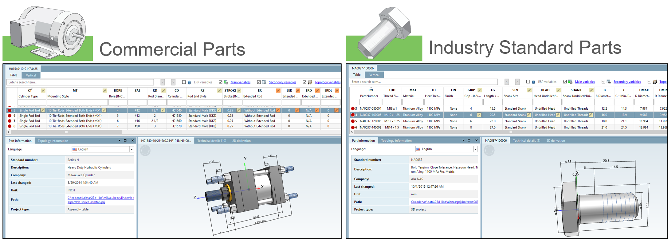 |
| Term: Center Plane of Feature | |
| Definition: The center plane of the unrelated Actual Mating Envelope of a feature. |
| Term: Certified | |
| Definition: Guaranteed to conform to protocols. |
| Term: Characteristic | |
| Definition: a control placed on an element of a feature such as its size, location or form, which may be a specification limit, a nominal with tolerance, a feature control frame, or some other numerical or non-numerical control. |
| Definition: An item of specialized supplemental information associated with a characteristic such as Criticality Classification, Product Requirement Associations, or Verification Plan Requirements. |
| Definition: A designator that labels a characteristic augmentation from its attributes. |
| Definition: A designator that labels a characteristic with its tag. |
| Term: Characteristic ID | |
| Definition: A human readable unique identifier. Characteristic IDs are assigned to tolerances within the Authoritative Technical Data to enable human readable tracking from native CAD data to derivative CAD data. The characteristic ID may also be consumed by downstream machine-readable equipment (e.g. inspection report generation). |
| Term: Characteristic Item | |
| Definition: a tolerance or specification applied to a feature or product that needs verification |
| Term: Characteristic Tag | |
| Definition: A tag used for a characteristic. |
| Definition: A designator that labels a characteristic augmentation from its attributes. |
| Term: Child Model | |
| Definition: A model that “trees” up into the next higher assembly/installation. |
| Term: Circular Runout | |
| Definition: The condition in which each circular element of a surface is at zero variation relative to a datum axis or axis of rotation established from the datum reference frame. |
| Term: Circularity | |
| Definition: The condition of a surface in which (a) for a feature other than a sphere, all points of each circumferential line created by the surface intersected by any plane perpendicular to the axis or spine (curved line) are equidistant from that axis or spine. (b) for a sphere, all points of the surface intersected by any plane passing through a common center are equidistant from that center. |
| Term: Classification Code | |
|
Definition: A designation assigned to product definition data that defines what product definition elements are included within the drawing graphic sheet, data set, or both.
NOTE: A drawing graphic sheet may be in either physical or electronic format. |
| Term: Classification Code 1 | |
|
Definition: Drawing Graphic Sheet With Optional Data Set
Identifies that product definition elements are located on the drawing graphic sheet. |
| Term: Classification Code 2 | |
|
Definition: Data Set With Model and Drawing Graphics Sheet
Identifies that product definition elements are located on a drawing graphic sheet. A computer is used as a tool to prepare the drawing graphics sheet and model. Product definition elements are located in the digital data and drawing graphic sheet.
|
| Term: Classification Code 3 | |
|
Definition: Data Set With Model and Simplified Drawing Graphics Sheet
Identifies a model with a simplified drawing graphic sheet used to expedite communication of common part features and to define nongeometric part definitions. |
| Term: Classification Code 4 | |
|
Definition: Data Set With Annotated Model and Drawing Graphics Sheet
Identifies that all product definition elements are located in both the digital data and drawing graphic sheet. |
| Term: Classification Code 5 | |
|
Definition: Data Set With Annotated Model and No Drawing Graphic Sheet
Identifies that all product definition elements are located in the data set. No drawing graphic sheet exists.
|
| Term: Coaxiality | |
| Definition: The condition in which the axis of the unrelated actual mating envelope (AME) or axis of the unrelated minimum material envelope, as applicable, of one or more surfaces of revolution is coincident with a datum axis or another feature axis. |
| Term: Commercial Drawing | |
| Definition: Is prepared by a commercial design activity, in accordance with that activity's documentation standards and practices, to support the development and manufacture of a commercially developed product. |
| Term: Commercial Item | CI |
|
| Definition: An existing product, material, component, subsystem, or system sold or traded to the general public during normal business operations at prices based on established catalog or market prices. |
| Term: Commercial and Government Entity Code | CAGE |
|
| Definition: A five-character code that provides a unique activity identifier used by the government for activity identification. This method of activity identification has also been widely adopted by industry. |
| Term: Company Standard | |
| Definition: A document produced by a company that establishes engineering and technical limitations and applications for items, materials, processes, methods, designs, and engineering practices unique to that particular company. |
| Term: Complex Feature | |
| Definition: A single surface of compound curvature or a collection of features. |
| Term: Complex Geometry | |
| Definition: A Combination of features that cannot easily be characterized by concise equations or algorithms (e.g., nonlinear, nonrepeating, random). |
| Term: Component | |
| Definition: A part or subassembly model that is assembled into an assembly or subassembly model. |  |
| Term: Computer Aided Engineering | CAE |
|
| Definition: The use of computers to aid in the software engineering process. CASE tools may include the application of software tools to software design, requirements tracing, code production, testing, document generation, and other software engineering activities. Assemblers and compilers are CASE tools. |
| Term: Computer Aided Manufacturing | CAM |
|
| Definition: Use of computer software to control and manage manufacturing processes, such as automatically coordinated operations of conveyor systems, cutting and forming machines, and riveting and welding machines. |
| Term: Conceptual Design Data | |
| Definition: Engineering design data which describe the engineering concepts on which a proposed technology or design approach is based. |
| Term: Conceptual Model | |
| Definition: The collection of abstractions, assumptions, and descriptions of physical components and processes representing the behavior of the reality of interest, which includes the RWS [Real-World System], its environment, and their relative behaviors. |
| Term: Configuration Item | CI |
|
| Definition: An aggregation of hardware, software, or both, that is designated for configuration management (CM) and treated as a single entity in the CM process. The entity within a configuration that satisfies an end use function and that can be uniquely identified at a given reference point. |
| Term: Conformance | |
| Definition: precise, text definition of a characteristic required to be present in a conforming implementation |
| Term: Constraint | |
| Definition: A limit to one or more degrees of freedom. |
| Term: Continuous Feature | CF |
|
| Definition: Two or more interrupted features designated with a CF symbol, indicating they are to be considered as a single feature. |
| Definition: Two or more regular features of size or an interrupted regular feature of size that is designated with a CF symbol, indicating they are to be considered as a single regular feature of size. |
| Term: Coordinate System | |
| Definition: A representation of a system to determine the position of geometric elements in space, e.g., Cartesian coordinate system. | 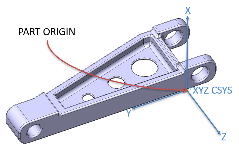 |
| Term: Coplanarity | |
| Definition: The condition of two or more surfaces having all elements in one plane. |
| Term: Copy | |
| Definition: Any reproduction or duplication, in any media, of an original. |
| Term: Core Model | |
| Definition: The essential minimum of data which are required to preserve the design intent for a given purpose. (NAS9300-003, 5.3.2.1) |
| Term: Costed Bill of Materials | Costed BOM |
|
| Definition: Bill of materials which includes component costs for each component of the product. These include values for all costing items of a material, sales order or base planning object. |
| Term: Courtesy Model | |
| Definition: An unauthorized artifact (e.g., model) provided to a recipient. |
| Term: Critical Application | |
| Definition: Uses where failure of the item would result in one or more of the following conditions: (a) risk of personal injury or endangerment of life (b) loss of or damage to equipment (c) degradation of performance to a point that would jeopardize its capacity to fulfill its intended function. |
| Term: Critical Characteristic | |
| Definition: A characteristic that analysis indicates is likely, if defective, to create or increase a hazard to human safety, or to result in failure of a system to perform a required function. |
| Term: Critical Issue | |
| Definition: Those aspects of a systems capability, operational, or technical and other aspects that must be questioned before a systems overall suitability can be known. Critical issues are of primary importance to the decision authority in reaching a decision to allow the system to advance into the next phase of development. |
| Definition: A process that is the only known manufacturing method that will result in the production of an acceptable item. |
| Term: Critical Note | |
| Definition: A note of great importance that appears on a 3D model. |
| Definition: Any feature, such as tolerance, finish, material composition, manufacturing, assembly, or inspection process or product that, if nonconforming or missing, could cause the failure or malfunction of the critical safety item. |
| Term: Critical Safety Item | CSI |
|
| Definition: A part, assembly, installation, or production system with one or more critical safety characteristics that, if not conforming to the design data or quality requirements, would result in an unsafe condition. |
| Term: Critical Safety Process | CSP |
|
| Definition: Any fabrication, manufacturing, assembly, installation, maintenance, repair, or other process or procedure that implements a safety design feature or satisfies system safety requirements. |
| Term: Criticality | |
| Definition: A relative measure of the consequences of a failure mode and its frequency of occurrence. |
| Term: Criticality Classification | CC |
|
| Definition: A characteristic augmentation that optionally designates a criticality. |
| Definition: A designator that labels a Criticality Classification. |
| Term: Criticality Designator | |
| Definition: A note of great importance that appears on a product definition. |
| Term: Current Design Activity | CDA |
|
| Definition: The design activity currently responsible for the design of an item. This may be the original design activity or a design activity to which the design responsibility has been transferred. |
| Term: Customer Requirement | |
| Definition: A requirement that address a customer's expectations for the functionality, performance, and quality of a product being developed. |
| Term: Cylindricity | |
| Definition: The condition of a surface of revolution in which all points of the surface are equidistant from a common axis. |
| Term: Data | |
| Definition: Information represented in a formal manner suitable for communication, interpretation, or processing by human beings or computers. |
| Term: Data Attributes | |
| Definition: The quantitative or qualitative characteristics of a data element. |
| Term: Data Exchange | |
| Definition: storing, accessing, transferring, and archiving of data |
| Term: Data Item Description | DID |
|
| Definition: A completed document defining the data deliverables required of a DOD contractor. A DID specifically defines the data content, format and intended use of the data with a primary objective of achieving standardization of data deliverables by the DOD. (MIL-STD-963). |
| Term: Data Object | |
| Definition: A collection of data treated as a single unit, such as a CAD model or file. |
| Term: Data Package | DP |
|
| Definition: A collection of 3D model geometry, annotations, attributes, and presentation states that includes a lightweight viewable file format that is intended for human readability. It may also contain derivate data and associated lists. | 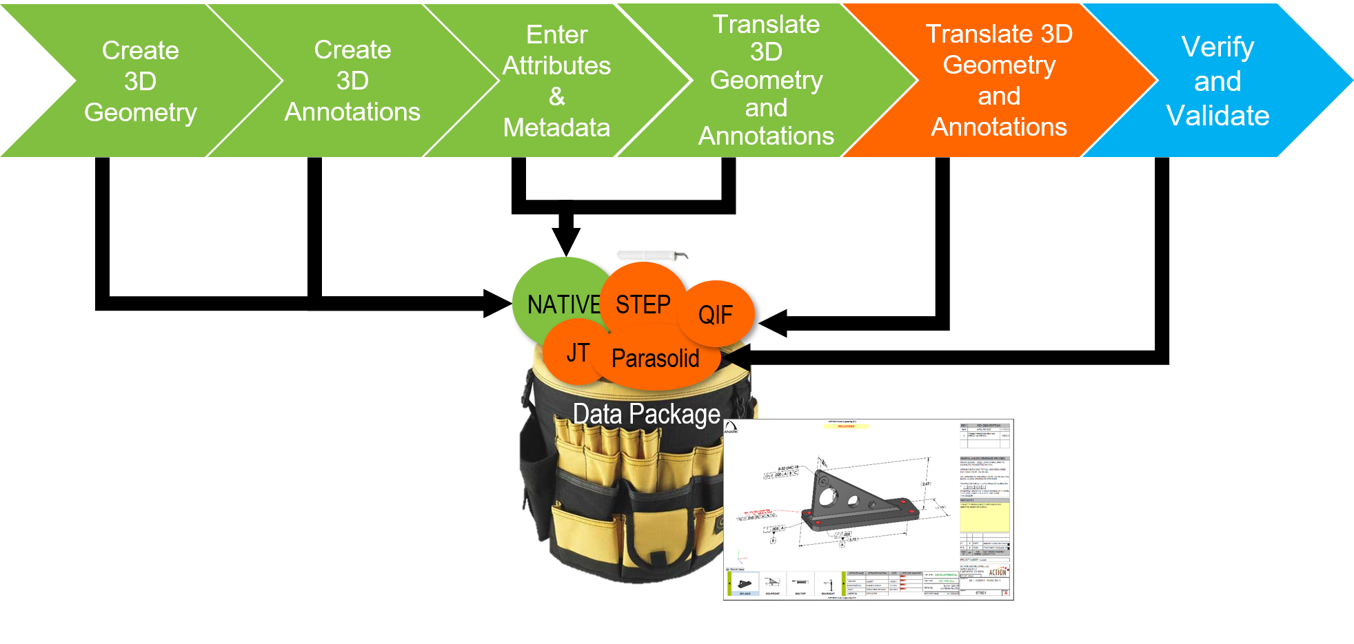 |
| Term: Data Silos | |
| Definition: Silos enable logistical organization, development of expertise, and management of similar mindsets; paper-based practices result in insolated & disconnected 2D data, while model-based practices use connected 3D data with a well-maintained digital thread. |
| Term: Dataset | |
| Definition: An identifiable collection of related data that serves a lifecycle activity. |
| Term: Datum | |
| Definition: A theoretically exact point, axis, line, plane, or combination thereof derived from the true geometric counterpart. |
| Term: Datum Axis | |
| Definition: The axis of a true geometric counterpart. |
| Term: Datum Center Plane | |
| Definition: The center plane of a true geometric counterpart. |
| Term: Datum Feature | |
| Definition: A feature that is identified with either a datum feature symbol or a datum target symbol(s). |
| Term: Datum Feature Simulator | |
| Definition: The physical boundary used to establish a simulated datum from a specified datum feature. NOTE: For example, a gage, a fixture element, and digital data (such as machine tables, surface plates, a mandrel, or a mathematical simulation) are not true planes, but are of sufficient quality that the planes derived from them are used to establish simulated datums. Datum feature simulators are used as the physical embodiment of the true geometric counterparts during manufacturing and inspection. See ASME Y14.43. |
| Term: Datum Feature Symbol | |
| Definition: The symbolic means of indicating a datum feature consists of an uppercase letter enclosed in a square or rectangular frame and a leader line extending from the frame to the feature, terminating with a triangle. |
| Term: Datum Reference Frame | |
| Definition: Three mutually perpendicular datum planes and three mutually perpendicular axes at the intersections of those planes. |
| Term: Datum Target | |
| Definition: The designated points, lines, or areas that are used in establishing a datum. |
| Term: Datum Target Symbol | |
| Definition: The symbolic means of indicating a datum target shall be a circle divided horizontally into halves. The lower half contains a letter identifying the associated datum, followed by the target number assigned sequentially starting with 1 for each datum. | 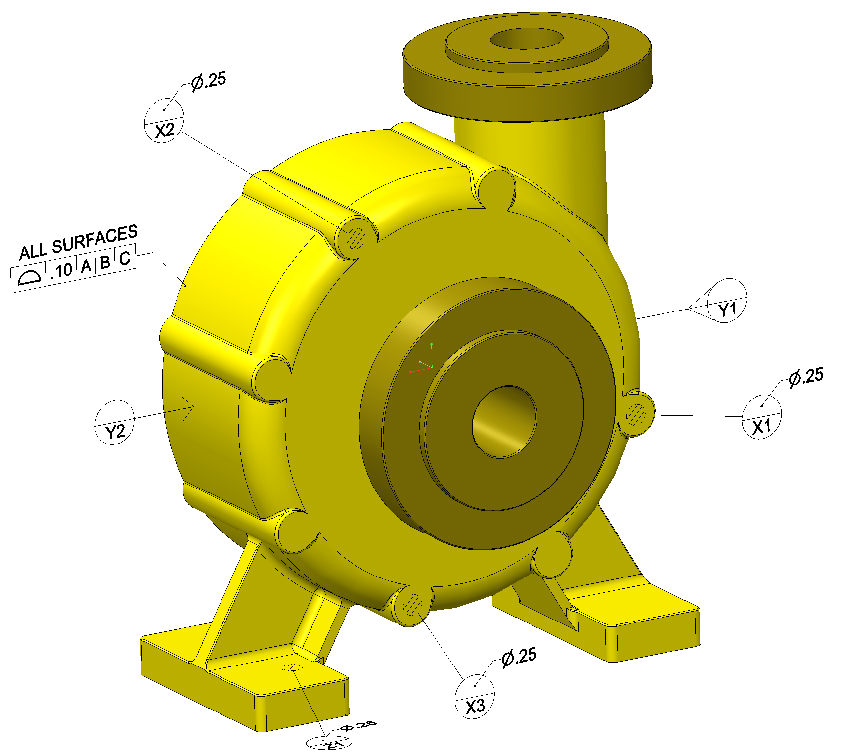 |
| Term: Derivative | |
| Definition: Data duplicated or extracted from the original. A copy of a derivative is also a derivative. |
| Term: Derivative Model | |
| Definition: A model created from a source model that may be transformed into a different format. |
| Definition: Viewing of 3D models for design reviews, cost estimating by suppliers, and other applications in which the fidelity of appearance but not a high degree of manufacturing accuracy are required. Once data has been translated to a form for visualization, it should no longer be used for manufacturing. Visualization formats include 3D PDF, Siemens PLM Software JT, Parametric Technologys Pro/View and Creo Visualization, and Autodesks DWF. Models used for visualization must look right and the annotations associated with them must be accurate. Visualization models are subject to the least stringent validation criteria because it will not be used for manufacturing or engineering changes. |
| Definition: A set of technical data generated from master technical data. Typically derivative technical data is created to change its format to suit a different purpose. For example converting master, native format data to neutral or viewable data (e.g. STEP, PDF, etc.) so as to allow it to be read by a wider range of software applications. Changes to derivative technical data originate on the master technical dataset. |
| Term: Derived Median Line | |
| Definition: An imperfect (abstract) line formed by the center points of all cross sections of the feature. These cross sections are normal (perpendicular) to the axis of the unrelated AME. |
| Term: Derived Median Plane | |
| Definition: An imperfect (abstract) plane formed by the center points of all line segments bounded by the feature. These line segments are normal (perpendicular) to the center plane of the unrelated AME. |
| Term: Design Activities | |
| Definition: Activities involved in designing a product. |
| Term: Design Activity | |
| Definition: An organization that has, or has had, responsibility for the design of an item. |
| Term: Design Activity Identification | DAI |
|
| Definition: The application of a unique identifier that distinguishes an activity or organization from another activity or organization. Examples of activity identification include activity name, activity name and address, or CAGE code. |
| Term: Design Authority | |
| Definition: The single source authority for the design model, annotations, and attributes. |
| Term: Design Characteristic | |
| Definition: Those dimensional, visual, functional, mechanical, and material features or properties, which describe and constitute the design of the article, as specified by drawing or DPD requirements. These characteristics can be measured, inspected, tested, or verified to determine conformance to the design requirements. Dimensional features include in-process locating features (e.g., target-machined or forged/cast dimensions on forgings and castings, weld/braze joint preparation necessary for acceptance of finished joint). Material features or properties may include processing variables and sequences, which are specified by the drawing or DPD (e.g., heat treat temperature, fluorescent penetrant class, ultrasonic scans, sequence of welding and heat treat). These provide assurance of intended characteristics that could not be otherwise defined. |
| Definition: A drawing or set of drawings and associated data that delineates the detailed engineering requirements of an end product necessary for the fabrication, assembly, inspection, and test of the item. |
| Term: Design Model | |
| Definition: The portion of the data set that contains model geometry and supplemental geometry. |
| Term: Design Parameters | |
| Definition: Qualitative and quantitative aspects of physical and functional characteristics of a component, device, product, or system that are input to its design process. Design parameters determine cost, design, and risk tradeoffs in the item’s development. |
| Term: Design Simulation | |
| Definition: Design simulation helps manufacturers verify and validate the intended function and manufacturability of a product under development in earlier stages of design. |
| Term: Design for Manufacturing and Assembly | DFMA |
|
| Definition: DFMA is an engineering methodology that focuses on simplifying the design of a product to improve ease of manufacture and efficiency of assembly. |
| Term: Design for X | DFX |
|
| Definition: An activity that optimizes a design for a goal. |
| Term: Designator | |
| Definition: A means to identify and set apart for a specific purpose. |
| Definition: Engineering design data which describe the physical and/or performance characteristics of a specific design approach to the extent necessary to permit the analytical evaluation of the ability of the design approach to meet specified requirements and enable the development, manufacture and testing of prototype or experimental material. |
| Term: Digital | |
| Definition: Data intended for interpretation by computer applications. |
| Term: Digital Artifact | |
| Definition: A product or output, in computer (i.e., digital) format, created within or generated from the digital engineering ecosystem. Digital artifacts provide data for alternative views to visualize, communicate, and deliver data, information, and knowledge to stakeholders. |
| Term: Digital Element | |
| Definition: Geometric element, feature, group of features, annotation, associated group, or attribute that exists in a data set. |
| Definition: A label or name used to specify a unique digital element. |
| Term: Digital Engineering | |
| Definition: A means of using and integrating digital models and the underlying data to support the development, test and evaluation, and sustainment of a system. |
| Definition: The ability to develop, validate, use, curate, and maintain technically accurate digital systems and models of systems, subsystems, and their components, at the appropriate level of fidelity to ensure test activities adequately simulate the environment in which a system will be deployed. |
| Definition: The interconnected infrastructure, environment, and methodology (process, methods, and tools) used to store, access, analyze, and visualize evolving system’s data and models to address the needs of the stakeholders. |
| Term: Digital Enterprise | |
| Definition: An organization that uses a digital thread to conduct business activities. |
| Term: Digital Manufacturing | |
| Definition: Digital manufacturing integrates simulation, 3D visualization, analytics and collaboration tools to create simultaneous product and manufacturing process definitions, enabling industries to design entire manufacturing processes digitally, fostering collaboration between engineers and designers. |
| Term: Digital Metrology | |
| Definition: The process of performing metrology operations on an end item using digital data which is connected, traceable, and automated. |
| Term: Digital Model | |
| Definition: A model that is digitally represented. |
| Definition: Requirements of any digital data files that disclose, directly or by reference, the physical or functional requirements, including data files that disclose the design or acceptance criteria of a product. Examples of DPD include the following: The digital definition and fully dimensioned two-dimensional (2D) drawing sheets. Three-dimensional (3D) data model and simplified or reduced content 2D drawing sheets. The 3D model with design characteristics displayed as text. Any other data files that define a product in its entirety. |
| Term: Digital Signature | |
| Definition: result of a cryptographic transformation of data that, when properly implemented, provides a mechanism for verifying origin authentication, data integrity and signatory non-repudiation |
| Term: Digital Thread | |
| Definition: A communication framework that connects data flows, which can be used to produce an integrated and holistic view of an asset’s data from physical and virtual systems (i.e., its Digital Twin) throughout its lifecycle across traditionally siloed functional perspectives. |
| Term: Digital Transformation | |
| Definition: Digital transformation is a strategic imperative for businesses seeking to remain competitive and relevant in today's evolving digital landscape. Embracing digital technologies and modernizing their operations, organizations unlock opportunities for growth and drive sustainable long-term success. |
| Term: Digital Twin | |
| Definition: A digital twin is an integrated data-driven virtual representation of real-world entities and processes, with synchronized interaction at a specified frequency and fidelity. |
| Term: Digitalization | |
| Definition: The process of moving information from paper to digital forms (e.g., computer files, connected data elements representing a product, managing a configuration and all its dependencies). Basically, the process of changing from analog to digital form. |
| Definition: Digitalization in education refers to the use of digital technology to teach students. |
| Term: Dimension | |
| Definition: A numerical value(s) or mathematical expression in appropriate units of measure used to define the shape, size, orientation, or location of a part feature or between part features. |
| Term: Direct Engineering | |
| Definition: Engineering effort directly related to specific end products. |
| Term: Direct Modeling | |
| Definition: A modeling method that allows designers to interact directly with the geometry of the model. |
| Definition: A dimension with an associated plus/minus tolerance or limit dimension values. NOTE: Where a plus/minus general tolerance is applied to a dimension, the dimension is considered a directly toleranced dimension. |
| Term: Distributed Product Description | DPD |
|
| Definition: Central elements in a collaborative environment that authoritatively maintain the system design and behavioral information for alternative designs as needed for Modeling and Simulation (M&S) analyses by all authorized users. In particular, the DPD should possess strong inter-networking capabilities to maintain coordinated system design (structural) and performance views of the system under development. It should incrementally reflect changed performance parameters in response to design changes and address the resulting performance impacts on system operations. |
| Term: Drawing | |
| Definition: An engineering document or digital data file(s) that discloses (directly or by reference), by means of graphic or textual presentations, or by combinations of both, the physical or functional requirements of an item. |  |
| Term: Drawing Format | |
| Definition: The arrangement and organization of information within a drawing. This includes such features as the size and arrangement of blocks, notes, lists, and revision information and use of optional or supplemental blocks. |
| Term: Drawing Graphic Sheet | |
| Definition: The two-dimensional geometric elements and annotations that define an item and the product definition elements of the sheet format in accordance with ASME Y14.1 or ASME Y14.1M. |  |
| Term: Drawing Requirement | |
| Definition: Requirements of the drawing and associated parts lists, specification, or purchasing document to which the product is to be produced from, including any notes, specifications, and lower-level drawings invoked. |
| Term: Drawing Tree | |
| Definition: A block diagram or indented list that identifies all drawings applicable to an end item or program and illustrates the next higher and subordinate relationships that exist between those drawings. |
| Term: Drawing-Based Characteristic | DBC |
|
| Definition: A characteristic, which is presented on a graphical drawing. |
| Term: Driven Characteristic | |
| Definition: A Product Characteristic, which is supplemented by a Product Requirement Association augmentation. |
| Term: Driven Dimension | |
| Definition: Dimensions in a drawing file derived from the 3D model. Driven dimensions reflect changes to part or assembly geometry, but you cannot modify their values in the drawing. The association is one-way; from the model to the drawing. |
| Term: Driving Dimension | |
| Definition: A dimension that when modified in the drawing is also modified in the 3D model from which it originated. |
| Term: Duplicate Original | |
| Definition: A replica of an engineering drawing created to serve as the official record of the item when the original has been lost. |
| Term: Electronic | |
| Definition: A computerized document intended for presentation to humans. |
| Term: Electronic Signature | |
| Definition: A defined method to sign an object in electronic environments. It provides means to authenticate the signatory and the signed object in an unambiguous and safe way by attaching to or logically associating data in electronic form to other electronic objects. (See NAS9300-005) |
| Term: Embellished Derivative | |
| Definition: The condition of a derivative being embellished from its source with respect to an intended use. |
| Term: End Item | |
| Definition: The final production product when assembled, or completed, and ready for issue or deployment. |
| Term: End Product | |
| Definition: An item, such as an individual part or assembly, in its final or completed state. |  |
| Term: Engineering Bill of Materials | eBOM |
|
| Definition: The engineering bill of materials reflects the design of the product rather than the manufacturing process of the product. eBOMs are typically driven from the CAD model and are usually centric to the final assemblies list of parts or components. |
| Definition: A proposed engineering change to the product and its configuration documentation, by which the change is described, justified, and submitted to a Configuration Approval Authority for approval/disapproval or deferral. |
| Term: Engineering Data | |
| Definition: Engineering documents such as drawings, associated lists, accompanying documents, specifications, standards, or other information prepared or used by a design activity and relating to the design, manufacture, procurement, testing, or inspection of items. |
| Term: Engineering Design Data | |
| Definition: Engineering drawings, 3Di viewables, native CAD models, neutral CAD models or a combination of these, which define an item by means of graphic and textual presentations, the physical and/or functional requirements of an item, sufficient to fulfill its TDP element and level requirements. Engineering design data comes in three levels corresponding to its TDP level requirements. |
| Term: Engineering Signature | |
| Definition: A digital signature with which the data producer asserts that the prepared data fits with the process and quality requirements from the engineering point of view. (NAS9300-005) |
| Term: Enterprise | |
| Definition: A supra-organization that participates in an endeavor. |
| Definition: Activities that enable an organization to act as a MBE, but do not directly add value to a product. |
| Term: Enterprise Identifier | EID |
|
| Definition: A unique identifier used to distinguish one activity or organization from another activity or organization. Examples of enterprise identifiers are: Commercial and Government Entity (CAGE) Code; Department of Defense Activity Address Code (DODAAC); Dun & Bradstreets Data Universal Numbering System (D-U-N-S); North Atlantic Treaty Organization (NATO) CAGE (NCAGE) Code; ISO/SAE WMI Code and GS1 Company Prefix. An enterprise identifier code is uniquely assigned to an activity by an issuing agency registered in accordance with procedures outlined in ISO/IEC 15459-2. An enterprise may be an entity such as a design activity, manufacturer, supplier, depot, program management office, or a third party. |
| Term: Enterprise Resource Planning | ERP |
|
| Definition: A system that manages as-routed data and is the authoritative source for schedule, producer information, and cost. |
| Term: Enterprise Simulation Management | ESM |
|
| Definition: Integrates and manages simulation and analysis data and processes across the product development processes. ESM’s primary components include knowledge capture and replication and integrated simulation management. Also called Simulation Data Management or Simulation Lifecycle Management. |
| Term: Envelope | |
| Definition: A part created to represent a predetermined set of components in an assembly. The envelope uses simple geometry to reduce system memory usage and looks similar to the components it represents. |
| Term: Envelope Drawing | |
| Definition: Product definition data that discloses the basic technical data and performance requirements necessary for development, or design selection of an item where it is desirable to have all features other than those shown on the drawing left to the ingenuity of the supplier. An envelope drawing does not establish item identification. |
| Term: Envelope Model | |
| Definition: A solid model representation of the outer shape of an assembly that is represented as a single part. | 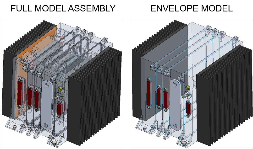 |
| Definition: A tolerance in which variation is permitted equally in both directions from the specified dimension or true profile. |
| Term: Equivalent Derivative | |
| Definition: The condition of a derivative being functionally equivalent to its source with respect to an intended use. |
| Term: Exchange Structure | |
| Definition: computer-interpretable format used for storing, accessing, transferring, and archiving data |
| Term: Externally Defined | |
|
Definition: Explicit identification of the definition given within another source
Note 1 to entry: That source provides all the information necessary to unambiguously recreate the element; the information can be referenced rather than recreated.
|
| Term: Family Tables | |
| Definition: A collection of parts (or assemblies or features) that are essentially similar, but deviate slightly in one or two aspects, such as size or detail features. For example, wood screws come in various sizes, but they all look alike and perform the same function. Thus, it is useful to think of them as a family of parts. Parts in Family Tables are also known as table-driven parts. |
| Term: Family of Products | |
| Definition: All products of the same classification, design, construction, material, type, etc., produced with the same production facilities, processes, and quality of material, under the same management and quality controls, but having the acceptable variety of physical and functional characteristics defined and specified in the applicable engineering documentation. |
| Term: Feature | |
| Definition: A physical portion of a part (such as a surface, pin outside diameter, hole, or slot) or its representation on drawings, models, or digital data files. |
| Term: Feature Axis | |
| Definition: The axis of the unrelated AME of a feature. |
| Term: Feature Control Frame | |
| Definition: A rectangle divided into compartments containing the geometric characteristic symbol followed by the tolerance value or description, modifiers, and any applicable datum feature references. |
| Term: Feature Reference Tag | |
| Definition: A tag used to identify a geometric feature, face, or element. |
| Term: Feature of Size | |
| Definition: A general term that is used in the ASME Y14.5 Standard to refer to instances in which both a regular and an irregular feature of size apply. |
| Term: Feature-Relating Tolerance Zone Framework | FRTZF |
|
| Definition: The tolerance zone framework that controls the basic relationship between the features in a pattern with that framework constrained in rotational degrees of freedom relative to any referenced datum features. |
| Term: Final Assembly | |
| Definition: The joining of the major sections to perform a complete unit. |
| Term: Final-Process Model | |
| Definition: The final process model for a process definition. |
| Term: Finite Element Method | |
| Definition: A numerical technique for finding approximate solutions to systems of partial differential equations. FEM is applied to calculations of stress, strain, and deflection, temperature distribution and heat transfer, electromagnetic and similar problems. FEM, also called finite element analysis (FEA), is characterized by the subdivision of solid objects into tetrahedral or hexahedral finite elements. Thin-walled objects may be approximated by two-dimensional shell elements having three or four sides. |
| Term: First Article Inspection | FAI |
|
| Definition: A planned, complete, independent, and documented inspection and verification process to ensure that prescribed production processes have produced an item conforming to engineering drawings, DPD, planning, purchase order, engineering specifications, and/or other applicable design documents. |
| Term: First Article Inspection Report | FAIR |
|
| Definition: The forms and package of documentation for a part number, subassembly, or assembly, including associated FAI results. |
| Term: First Production Run | |
| Definition: The initial group of one or more parts that are the result of a planned process designed to be used for future production of these same parts. |
| Term: Flatness | |
| Definition: The condition of a surface or derived median plane having all elements in one plane. |
| Term: Free State | |
| Definition: The condition in which no externally introduced forces other than gravity are applied to a part. |
| Term: Free Zone | |
| Definition: A type of bounded volume region that encloses the entire part and in which other parts cannot be located or intersected. |
| Term: Fully Annotated Model | |
| Definition: A model that includes every basic dimension and tolerance value necessary to produce the part by visual inspection of the annotated model alone. Also known as a 3D Drawing. |
| Definition: The formal examination of functional characteristics of a configuration item, or system, to verify that the item has achieved the requirements specified in its functional and/or allocated configuration documentation. |
| Term: General Tag | |
| Definition: A characteristic tag used for a non-product characteristic or general usage. |
| Term: Generative Design | |
| Definition: An iterative software-based process that uses human entered constraints and incorporates analysis, machine-learning, and simulations to interpret design requirements for production of multiple 3D geometric models for user evaluation. |
| Term: Geometric | |
|
Definition: related to shape information
EXAMPLE points, curves, surfaces, and volumes |
| Term: Geometric Characteristic | |
|
Definition: a concept characterizing the size, form, orientation or location of a feature or of a component of a feature
EXAMPLE diameter, flatness, parallelism, or position. |
| Term: Geometric Dimensions & Tolerances | GD&T |
|
| Definition: A general term for a system of applying dimensional annotations and tolerances to drawings or models defined by ANSI Standard Y14.5. |
| Term: Geometric Element | |
| Definition: A discrete entity (e.g., point, line, curve, plane, surface, solid, volume, vector, coordinate system) used in a digital data set to represent or present physical features of the product definition. |
| Term: Geometric Model | |
| Definition: The set of data and resources used to represent the precise size, position, and shape of an object, often a production. |
| Term: Geometric Tolerance | GT, GeoTol |
|
| Definition: A tolerance indicated using a geometric characteristic symbol. |
| Term: Geometry | |
| Definition: Geometry consists of the mathematical description of individual part surfaces. Modern CAD systems employ what is called the boundary representation method for describing model geometry. Boundary representations consist of curves, surfaces, edges, and faces. In a valid model, the faces meet at the edges to form a closed volume. |
| Term: Geometry State | |
| Definition: The level of detail of the geometry as represented in a model. |
| Term: Gradient Control | |
| Definition: Specifies, with tolerance, how physical characteristics are varied spatially (e.g., changes in material composition, color, density, porosity, or unit cell size). |
| Term: Graphic | |
| Definition: Pictorial representation of a 3D model or 2D drawing. Generally it is captured as a screen shot. The image can be isometric or planar, cartoon-like, 3D, realistic or line art. |
| Term: History Tree | |
| Definition: A hierarchical diagram of 3D model features that shows their relationships and the order in which they were created. |
| Term: In-Process Model | |
| Definition: The intermediate process model(s) with a process definition. |
| Term: Industrial Internet of Things | IIoT |
|
| Definition: Industrial Internet of Things (IIoT), also known as Industry 4.0, is the application of an IoT framework to devices and machines within manufacturing. The IIoT is part of a larger concept known as the Internet of Things (IoT). The IoT is a network of intelligent computers, devices, and objects that collect and share huge amounts of data. The collected data is sent to a central Cloud-based service where it is aggregated with other data and then shared with end users in a helpful way. |
| Term: Industry 4.0 | |
| Definition: The fourth industrial revolution, occurring now, is manufacturing operations digitally transformed to leverage connected data, machines, and people. A connected factory may use Additive Manufacturing (AM), cybersecurity, Artificial Intelligence (AI), Augmented Reality (AR), autonomous robots, big data analytics, cloud computing, the Internet of Things (IoT), Machine Learning (ML), simulation, and technologies not yet invented to reduce waste in their processes. |
| Term: Information | |
| Definition: Facts, concepts, or instructions |
| Term: Information Model | |
|
Definition: Formal model of information
Note 1 to entry: In ISO 10303, an information model is based on the Object-relationship modeling technique that organizes the product data as represented in different system aspects.
Note 2 to entry: In ISO 10303, information models are developed using EXPRESS modeling language.
EXAMPLE ISO 10303-242.
|
| Term: Inheritance Model | |
| Definition: A derivative model with one-way associative propagation of source model changes. |
| Term: Inner Boundary | IB |
|
| Definition: A worst-case boundary generated by the collective effects of the smallest feature of size (MMC for an internal feature of size, LMC for an external feature of size) and the applicable geometric tolerance. |
| Term: Inseparable Assembly | |
| Definition: One item, or two or more items joined together, that is not normally subject to disassembly without destruction or impairment of designed use (e.g., transistor, composition resistor, screw, transformer, and gear). |
| Term: Inseparable Part Model | |
| Definition: 3D CAD with two or more bodies and/or two or more Mono-Detail Models that represent an inseparable assembly (e.g., weldment). |
| Term: Inspection | |
| Definition: a measurement of characteristics on a physical part to determine whether the features are within allowed tolerance, commonly in order to accept or reject the part |
| Term: Inspection Requirement | |
| Definition: A tolerance or specification applied to a part feature or product that requires verification. |
| Term: Inspection Traceability | |
| Definition: Information about the circumstances of a quality measurement process |
| Term: Installation Assembly | |
| Definition: A collection of part and assembly models, combined in an assembly for the sole purpose of describing how a component or subassembly mounts in a very large structure. This assembly does not have a next higher assembly, nor is it typically the top assembly. |
| Term: Installation Model | |
| Definition: A model in which the product described is an installation, showing parts or assemblies and a partial or complete representation of the installation site. |
| Term: Instance | |
| Definition: Each instantiation of a component is called an instance. It may appear that the part model (component) is copied several times within a single assembly, yet the other representations are merely visualizations of the source data. | 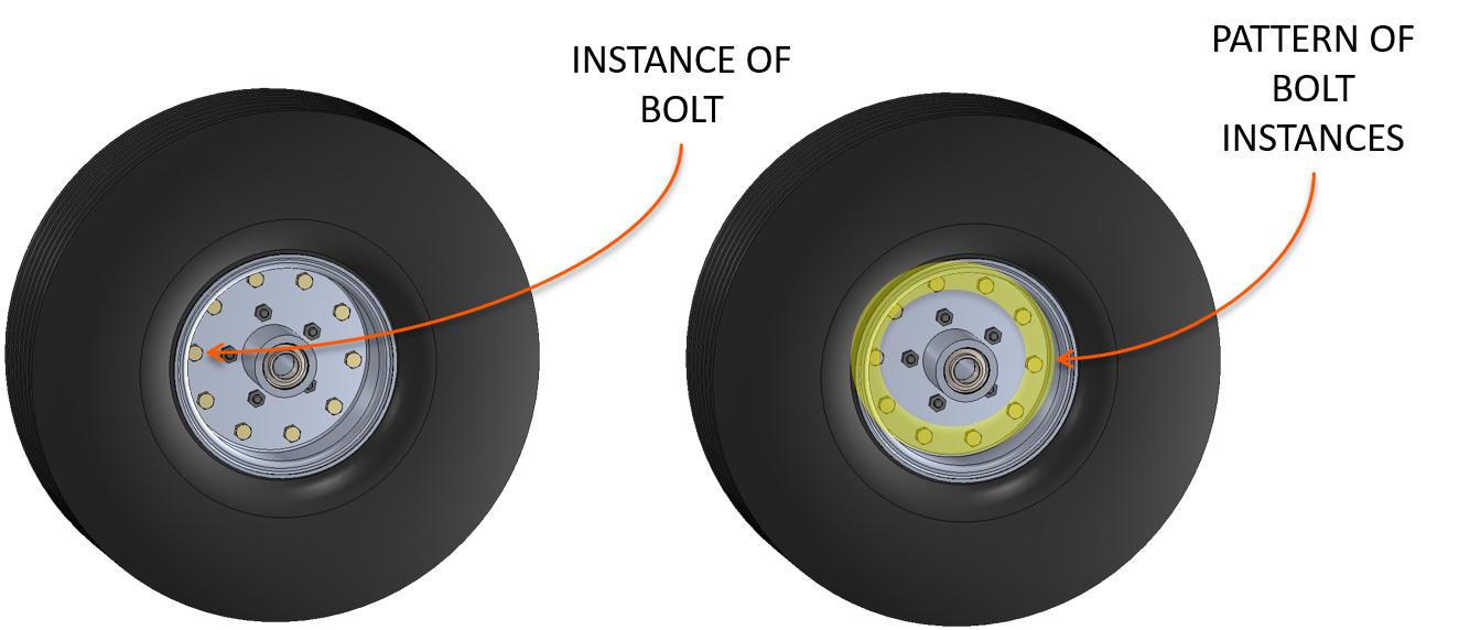 |
| Term: Integral Parts List | |
| Definition: A parts list prepared and revised as part of an engineering drawing. |
| Term: Inter-part References | |
| Definition: An associative link to a part external to the one being worked on. These references are sometimes called external references. For example, a hole may reference its centerline location from another part, creating an associated link from the hole feature to the other part. |
| Term: Interactive | |
| Definition: A mode of operation performed by a person interacting with automation. |
| Term: Interactive Parts List | |
| Definition: An automatically generated parts list from the CAD BOM that is optimized for the human user experience and persists digital associativity between the component and the parts list. The purpose is for the human reader to read, view, and navigate the parts list information within the context of the geometry and components. |
| Term: Interchangeability | |
| Definition: A condition that exists when two or more items possess such functional and physical characteristics as to be equivalent in performance and durability, are capable of being exchanged one for the other without alteration on the items themselves or of adjoining items, except for adjustment, and without selection for fit and performance. |
| Term: Interchangeable Item | |
| Definition: An item that possesses functional and physical characteristics equivalent in performance to another item of similar or identical purposes, and is capable of being exchanged for the other item without selection for fit or performance, and without alteration of the items themselves or of adjoining items, except for adjustment. |
| Term: Interface | |
| Definition: The functional and physical characteristics required to exist at a common boundary or connection between persons, between systems, or between persons and systems. A system external to the system being analyzed that provides a common boundary or service that is necessary for the other system to perform its mission in an undergraded mode, e.g., a system that supplies power, cooling, heating, air services, or input signals. |
| Term: Interruption | |
| Definition: A gap or gaps in a feature that divide it into two or more features (e.g., a slot or a groove). |
| Definition: There are two types of irregular features of size, as follows: (a) a directly toleranced feature or collection of features that may contain or be contained by an unrelated AME that is a sphere, cylinder, or pair of parallel planes. (b) a directly toleranced feature or collection of features that may contain or be contained by an unrelated AME other than a sphere, cylinder, or pair of parallel planes. |
| Term: Item | |
| Definition: A nonspecific term used to denote any unit or product, including materials, parts, assemblies, equipment, accessories, and computer software. |
| Term: Item Identification | |
| Definition: The Part or Identifying Number (PIN) for a specific item along with the original Design Activity Identification (DAI). |
| Term: Key Characteristic | |
| Definition: a characteristic of a feature, material, process, or part whose variation has a significant influence on product fit/function, safety/compliance, performance, service life, or manufacturability |
| Term: Large Sized Assemblies | |
| Definition: An assembly which has a total of all components (Company, Industry (including fasteners), Supplier), including all the instances (not unique parts) in the assembly are between 200 and 1000 parts. |
| Term: Lattice Structures | |
| Definition: Three dimensional geometric arrangement composed of connective links between vertices (points) creating a functional structure. |
| Term: Least Material Boundary | LMB |
|
| Definition: The worst-case boundary that exists on or inside the material of a feature(s) and is defined by the combined effects of size and geometric tolerances. |
| Term: Least Material Condition | LMC |
|
| Definition: The condition in which a feature of size contains the least amount of material within the stated limits of size, e.g., maximum hole diameter or minimum shaft diameter. |
| Term: Lifecycle Activity | |
| Definition: An activity related to a product lifecycle. |  |
| Term: Lifecycle Data | |
| Definition: Lifecycle Data consist of information that describes the state of the part within a controlled procedure for development, review, release for manufacture, retention for maintenance and upgrades, and retirement and disposal. For example, the revision level and release date are lifecycle data that describe the administrative state of the part and change as the product moves through its review and approval cycle. Lifecycle data dont describe properties inherent in the part (such as the material type or manufacturer) that are necessary information to make or procure the part. |  |
| Term: Lifecycle Management | LCM |
|
| Definition: A management process applied throughout the life of a system that bases all programmatic decisions on the anticipated mission-related and economic benefits derived over the life of the system. It includes the implementation, management, and oversight by the designated Program Manager (PM) of all activities associated with the acquisition, development, production, fielding, sustainment, and disposal of a DoD system across its life cycle. |
| Term: Limited Design Disclosure Models | LDDM |
|
| Definition: A 3D CAD data set sufficiently defined to provide a visual understanding of the item, but which does not contain full design disclosure. Generally external interface characteristics and features such as weight and center of gravity will be sufficiently defined for the intended purpose. Sometimes referred to as an envelope model, shrink-wrap model or cosmetic model. |
| Term: Limits of Size | |
| Definition: The specified maximum and minimum sizes. |
| Term: Long Term Archiving | |
| Definition: Storage of a copy of data in an appropriate way for record, certification and legal purposes. The data will be preserved and kept available for a use within the archive and possibly for further re-use. With certified conversion processes, the native data representation generated by the source system can be converted into a representation which is appropriate for long term archiving. To fulfill legal and certification requirements, the stored form can be an accurate or approximate representation of the source. Integrity must be ensured by a digital signature. The data is retained over the long term. Invariance is mandatory. Business, legal and certification requirements are covered. (NAS9300-003, 3.2.5) |
| Term: Long Term Archiving and Retrieval | LOTAR |
|
| Definition: A capability that preserves information and makes it available for communities of interest. |
| Term: MBD Dataset | |
| Definition: A product definition dataset that includes a model-based definition. |
| Term: MBE Maturity Index | |
| Definition: A tool that an organization uses to assess itself as, and facilitate transition to, a model-based enterprise. |
| Term: Major Assembly | |
| Definition: An operation in the construction of a section that joins a number of subassemblies. |
| Term: Management Data | |
| Definition: The data required for the release, control, and storage of product definition data as well as other relevant engineering data. |
| Term: Manual | |
| Definition: A mode of operation performed by a person without automation. |
| Term: Manufacturing | |
| Definition: The process of making an item using machinery, often on a large scale, and with division of labor. |
| Term: Manufacturing Activities | |
| Definition: Activities involved in making a product. |
| Term: Manufacturing Authority | |
| Definition: The single source authority for manufacturing. It is a connected derivation of the Design Authority model. Model data is derived from the design authority, but manipulated, translated, verified, and synced as required by the change management process back to the design authority. |
| Term: Manufacturing Bill of Materials | mBOM |
|
| Definition: The manufacturing bill of materials reflects the manufacturing process of the product rather than the design of the product. mBOMs are typically driven by the eBOM and also include all items related to the end product, including packaging or shipping. |
| Term: Manufacturing Execution System | MES |
|
| Definition: A system that manages as-built manufacturing information and is the authoritative source for execution records, assembly records, non-conformance records, and dimensional inspection records. It most often captures real-time data. |
| Term: Manufacturing Model | |
| Definition: May contain some or all of the Product Model data elements but will vary based on the manufacturing needs of the product. For example, it may be a single 3D solid model in neutral format containing only geometry. The elements contained in the Manufacturing Model are translated and verified from and against the Design Authority model. |
| Term: Manufacturing Operations Management | MOM |
|
| Definition: Software providing full visibility into manufacturing processes to optimize the efficiency and effectiveness of end-to-end manufacturing processes. |
| Term: Manufacturing Plans | |
| Definition: A set of data defining the process flow and test requirements for new product to be manufactured, which identifies the people, equipment, and facilities required. |
| Definition: A structured evaluation of a technology, component, manufacturing process, weapon system or subsystem performed to define the current level of manufacturing maturity, identify maturity shortfalls and associated costs and risks and to provide the basis for manufacturing maturation and risk management. |
| Term: Manufacturing Readiness Level | MRL |
|
| Definition: A measure used to assess the maturity of a given technology, component or system from a manufacturing prospective. The purpose of MRLs is to provide decision makers at all levels with a common understanding of the relative maturity and attendant risks associated with the manufacturing technologies, products, and processes under consideration. There are ten MRLs, with MRL 1 being the least mature and MRL 10 being the most mature. |
| Term: Manufacturing Resource Planning | MRP |
|
| Definition: A system that manages as-planned data and is the authoritative source for the mBOM, inventory, and equipment. |
| Definition: information about the circumstances of a manufacturing process. |
| Term: Manufacturing Work Instructions | MWI |
|
| Definition: A controlled set of instructions that describe in detail how particular tasks, procedures, or processes must be performed; provide a referenced, repeatable framework for communicating the steps needed to complete a task. |
| Term: Master | |
| Definition: A set of technical data which is the controlling source for any subsequent technical data output. All changes to the technical data must originate on the master technical dataset. There can be only one instance of the master technical data which is typically in the native CAD format and maintained by the current design activity. |
| Term: Master Drawing | |
| Definition: A document that shows the dimensional limits or grid locations applicable to any or all parts of a rigid or flexible printed board, including the arrangements of conductive and nonconductive patterns or elements, size, type, and location of holes; and any other information necessary to describe the product to be fabricated (see IPC T-150). |
| Term: Master Technical Data | |
| Definition: A set of technical data which is the controlling source for any subsequent technical data output. All changes to the technical data must originate on the master technical dataset. There can be only one instance of the master technical data which is typically in the native CAD format and maintained by the current design activity. |
| Term: Materials Requirements Planning | MRP |
|
| Definition: A methodology and system used to plan and manage manufacturing operations. The BOM for products released to manufacturing and the product routing definition are key parts of the MRP system’s database. |
| Term: Maturity Level | |
| Definition: In the MBE Maturity Index, a state of maturity that contains a set of assertions. |
| Term: Maturity State | |
| Definition: The condition of the design maturity for the specified use of the data set within the product life cycle. |
| Term: Maximum Material Boundary | MMB |
|
| Definition: The worst-case boundary that exists on or outside the material of a feature(s) and is defined by the combined effects of size and geometric tolerances. |
| Term: Maximum Material Condition | MMC |
|
| Definition: The condition in which a feature of size contains the maximum amount of material within the stated limits of size, e.g., minimum hole diameter or maximum shaft diameter. |
| Term: Measurement | |
| Definition: an estimate of a dimension associated with a feature or features on a physical part generated using a physical device |
| Term: Measurement Device | |
|
Definition: a measurement resource that provides an indication for a dimensional characteristic of a workpiece
Note 1 to entry: This indication may either be a value (variables) or simply conformance (attributes).
|
| Term: Measurement Plan | |
| Definition: a complete plan that contains information on what and how to measure |
| Term: Measurement Resource | |
| Definition: a piece of dimensional metrology equipment that can be used to measure features and/or characteristics on a workpiece |
| Term: Measurement Result | |
|
Definition: the measured value of an actual feature or characteristic
Note 1 to entry: A measurement result is obtained by measuring a feature or characteristic with a measurement resource. |
| Term: Medium Sized Assemblies | |
| Definition: An assembly which has a total of all components (Company, Industry (including fasteners), Supplier), including all the instances (not unique parts) in the assembly are between 200 and 1000 parts. |
| Term: Metadata | |
| Definition: Data about data. For example, the file name is meta data about a CAD design held as a file. |
| Term: Metadata Elements | |
| Definition: Organizational elements that capture data providing information about a product definition data set. |
| Term: Model | |
| Definition: The portion of the data set that contains model geometry and supplemental geometry. | 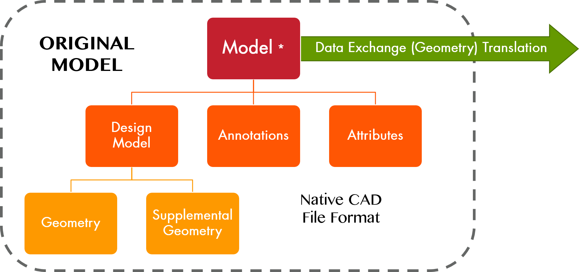 |
| Term: Model Geometry | |
| Definition: Geometric elements used to represent the definition of an item. |
| Term: Model Precision | |
| Definition: The highest number of significant digits set in the CAD model document. |
| Term: Model Schema | |
| Definition: An organization, grouping, naming convention and direction for completeness of models, annotations, attributes and metadata, included in the original model. These basic building blocks facilitate accurate archival and data exchange of TDP Type: 3D. |
| Term: Model Tree | |
| Definition: A Model Tree is a list of every feature in a part file including the datums and coordinate system. Creo Parametric displays the model structure in a hierarchical tree format with the current part or assembly as root object at the top of the tree. The subordinate parts or features are displayed below the root object. |
| Term: Model Value | |
| Definition: The numerical value derived by interrogating the model that quantifies the form and spatial relationships of the geometry composing a model, or assembly of models, to the precision [number of decimal places] of the computer system. |
| Term: Model-Based Characteristic | MBC |
|
| Definition: A characteristic, which is represented within a model-based definition model. |
| Term: Model-Based Definition | MBD |
|
| Definition: An annotated model and its associated data that define the product in a manner that can be used effectively without a drawing graphic sheet. |
| Term: Model-Based Engineering | MBE |
|
| Definition: A process that uses models throughout the product lifecycle. |
| Term: Model-Based Enterprise | MBE |
|
| Definition: An organization that uses digital methodologies as the foundation to enable deployment of products from concept to disposal. |
| Term: Model-Based Environment | MBE |
|
| Definition: An ecosystem defined by software, hardware, infrastructure, and people that supports both a Model-Based Engineering approach, and a Model Based Enterprise. |
| Term: Model-Based Manufacturing | MBM |
|
|
Definition: An environment [in that] the Design Data can be consumed by the value stream to plan, produce, fabricate, assemble, inspect and certify, [and] maintain and sustain parts and assemblies to meet requirements.
T. D. Hedberg Jr., M. E. Sharp, T. M. M. Maw, M. M. Helu, M. M. Rahman, S. Jadhav, J. J. Whicker & A. Barnard Feeney (2021): Defining requirements for integrating information between design, manufacturing, and inspection, International Journal of Production Research, DOI: 10.1080/00207543.2021.1920057. |
| Term: Model-Based Quality | MBQ |
|
|
Definition: The conformance of the physical product and process to the requirements of digital product definitions and process specifications using measurement planning, execution, and evaluation in combination with 3D annotated models and associated data.
T. D. Hedberg Jr., M. E. Sharp, T. M. M. Maw, M. M. Helu, M. M. Rahman, S. Jadhav, J. J. Whicker & A. Barnard Feeney (2021): Defining requirements for integrating information between design, manufacturing, and inspection, International Journal of Production Research, DOI: 10.1080/00207543.2021.1920057. |
| Term: Model-Based Systems Engineering | MBSE |
|
| Definition: Systems Engineering is a transdisciplinary and integrative approach to enable the successful realization, use, and retirement of engineered systems, using systems principles and concepts, and scientific, technological, and management methods. |
| Definition: An acquisition and design strategy consisting of a technical architecture that uses system interfaces compliant with widely supported and consensus-based standards (if available and suitable). The strategy supports a modular, loosely coupled and highly cohesive system structure that allows severable system components at the appropriate level to be incrementally added, removed, or replaced throughout the life cycle of a system platform to afford opportunities for enhanced competition and innovation. |
| Term: Mono-Detail Model | |
| Definition: 3D CAD that represents a single piece part. |
| Term: Multiple Characteristics | |
| Definition: Identical characteristics that occur at more than one location (e.g., 4 places), but are established by a single set of drawing or DPD requirements (e.g., rivet hole size, dovetail slots, corner radii, chemical milling pocket thickness). |
| Term: Native | |
| Definition: A 3D model in the (usually proprietary) format of the CAD system in which it was originally derived or modeled. |
| Term: Native CAD Data | |
| Definition: CAD data as created in its original authoring software format. In general, only the original authoring software format is capable of reading, editing and interpreting native CAD data. (Examples: CREO, CATIA, Autodesk, SolidWorks, etc.) Generally native CAD data is the only format suitable to serve as master technical data. Native CAD data may also serve as authoritative technical data. |
| Term: Native Format | |
| Definition: The format in which a software application stores its data, where that format is part of the design of the software. |
| Term: Native Model | |
| Definition: A model in the format of its originating software application (e.g., Creo). |
| Term: Nesting | |
| Definition: Situation when parts are made in one build cycle and are located such that their bounding boxes, arbitrarily oriented or otherwise, will overlap. |
| Term: Neutral | |
| Definition: independent of a specific computer system |
| Term: Neutral CAD Data | |
| Definition: CAD data which is derived from the native format and converted into a format which can be imported into other CAD software. Neutral CAD data is created to a widely available national or international standard (e.g. STEP). In general, neutral CAD data cannot serve as master technical data but may serve as either reference technical data or authoritative technical data. |
| Term: Nominal Geometry | |
| Definition: The theoretically perfect representation of a design's geometry as defined by the features' nominal sizes and basic dimensions. |
| Term: Nominal Size | |
| Definition: The designation used for purposes of general identification. (USAS B4.1) |
| Definition: A standardization document developed by a private sector association, organization or technical society which plans, develops, establishes or coordinates standards, specifications, handbooks or related documents. Company standards are not considered as non-Government standardization documents. |
| Term: Nonpart Drawing | |
| Definition: An engineering drawing that provides requirements, such as procedures or instructions, applicable to an item when it is not convenient to include this information on the applicable part drawing (e.g., a test requirements drawing or logic diagram). |
| Definition: An MMB and an LMB, where at least one boundary is a specified shape that is not a uniform offset from true profile. |
| Term: Notes | |
| Definition: Textual information that further delineates the requirements of the item represented. |
| Term: Open Standard | |
| Definition: Widely accepted and supported standards set by recognized standards organizations or the marketplace. These standards support interoperability, portability, and scalability and are equally available to the public at no cost or with a moderate license fee. |
| Term: Open System | |
| Definition: A system whose technical architecture adopts open standards and supports a modular, loosely coupled, and highly cohesive system structure. This modular open architecture includes publishing of key interfaces within the system and relevant design disclosure. |
| Term: Operation Characteristic | OC |
|
| Definition: A characteristic, which is created to identify an operation or process requirement for the product realization process of a product or of a feature of a product. |
| Term: Organizational Change Management | OCM |
|
| Definition: The mechanisms that integrates change and the ability to adapt change within an organization. |
| Term: Organizational Element | |
| Definition: A nongeometric model element selected for organization or grouping by a standardized method. |
| Term: Organizational Method | |
| Definition: A non-geometric model element selected for organization or grouping by a standardized method. |
| Term: Original | |
| Definition: The current design activity’s reproducible drawing or data set on which is kept the revision record recognized as official. |
| Term: Original Design Activity | ODA |
|
| Definition: The design activity originally responsible for the design and identification of an item whose drawing number and design activity identification is shown in the title block of the drawings and associated documents. |
| Term: Original Model | |
| Definition: Originating 3D Model, generally in native CAD software format, that is the working model for changes to geometry, annotations and attributes. From the original model flows the product model which is controlled as the record of authority. All data elements within the model maintain associativity to one another. |
| Term: Original Product Model | |
| Definition: The model used to keep the design intent for Long Term Archiving in the context of certification & legal requirements for proof. |
| Term: Orthographic View | |
| Definition: An orthographic view is the figure outlined upon the projection plane by means of the system of orthographic projection. Orthographic views may be constructed, or they may be saved views that are automatically gen-erated from models or design models. Orthographic view requirements apply equally to constructed and automatically generated views unless exception is stated. |
| Term: Outer Boundary | OB |
|
| Definition: A worst-case boundary generated by the collective effects of the largest feature of size (LMC for an internal feature of size, MMC for an external feature of size) and the applicable geometric tolerance. |
| Term: PDM System | Product Data Management System |
|
| Definition: An information system that implements product data management. |
| Term: Parallelism | |
| Definition: The condition of a line element, surface, tangent plane, center plane of a feature, or feature axis at an implied or specified basic 0° (parallel) angle relative to one or more datum planes or datum axes. |
| Term: Parameter | |
| Definition: A variable in the CAD system. |
| Term: Parametric | |
| Definition: A term used to classify curves for which the path is described by a mathematical function rather than a set of coordinates. A parameter within the function (often specified as u or v) is varied from 0 to 1 to define all the coordinate points along the curve. |
| Term: Parametric Assembly | |
| Definition: An assembly in which a component position updates as the referenced components move or change. |
| Term: Parametric Modeling | |
| Definition: A modeling process with the ability to change the shape of model geometry as soon as the dimension value is modified. |
| Term: Parent Model | |
| Definition: A model into which child models “tree” up. Also referred to as the next higher assembly/installation. |
| Term: Part | |
| Definition: One item, or two or more items joined together, that is not normally subject to disassembly without destruction or impairment of designed use (e.g., transistor, composition resistor, screw, transformer, and gear). | 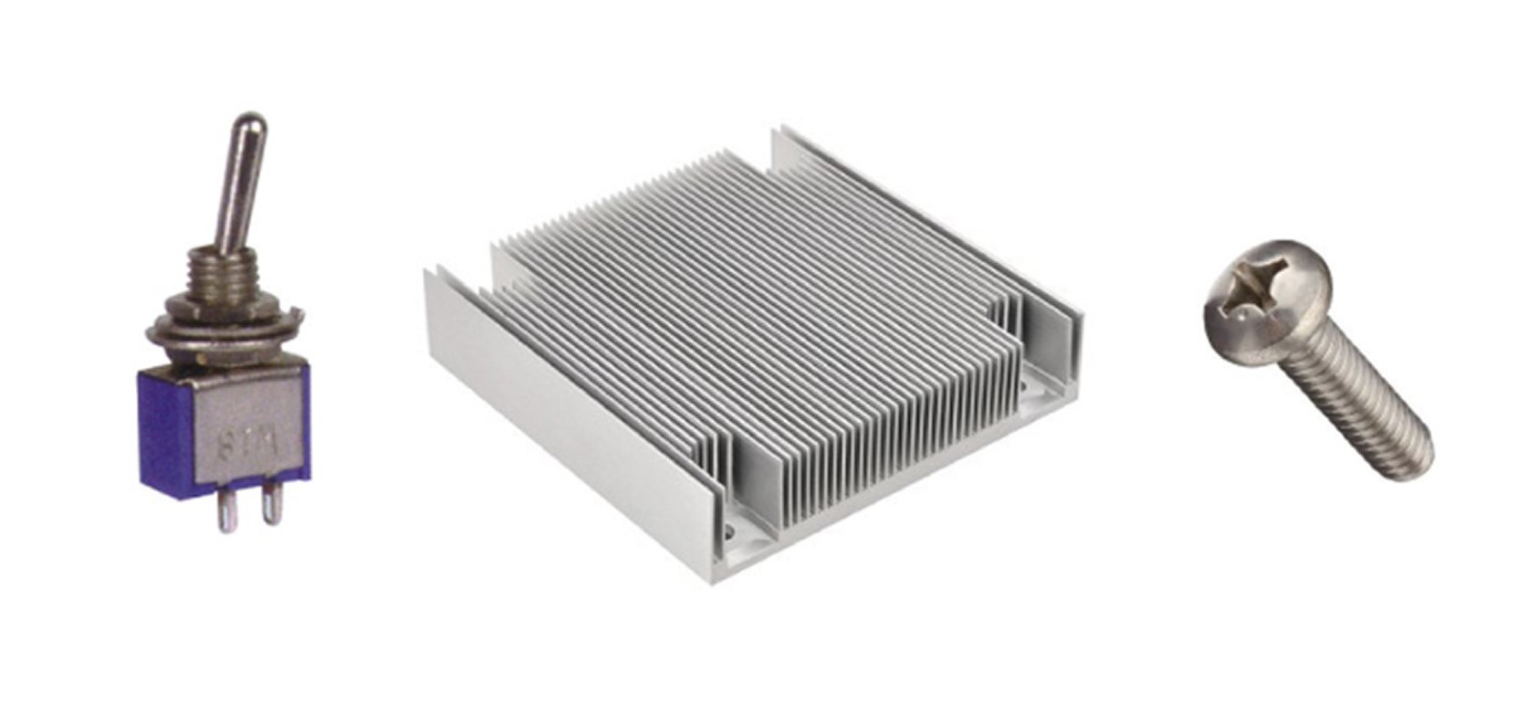 |
| Term: Part Model | |
| Definition: A 3D model representation of a single hardware item. |
| Term: Part or Identifying Number | PIN |
|
| Definition: The identifier assigned by the original design activity or by the controlling nationally recognized standard that uniquely identifies, relative to that design activity, a specific item. |
| Term: Part-Centric | |
| Definition: An organizing principle that enables product data management to relate all product lifecycle data to a single point of reference. |
| Term: Parts List | PL |
|
| Definition: A tabulation of all parts and bulk materials used in the item(s), except those materials that support a process and are not retained, such as cleaning solvents and masking materials. NOTE: Other terms used to describe a parts list are list of materials, bill of materials, stock list, and item list. | 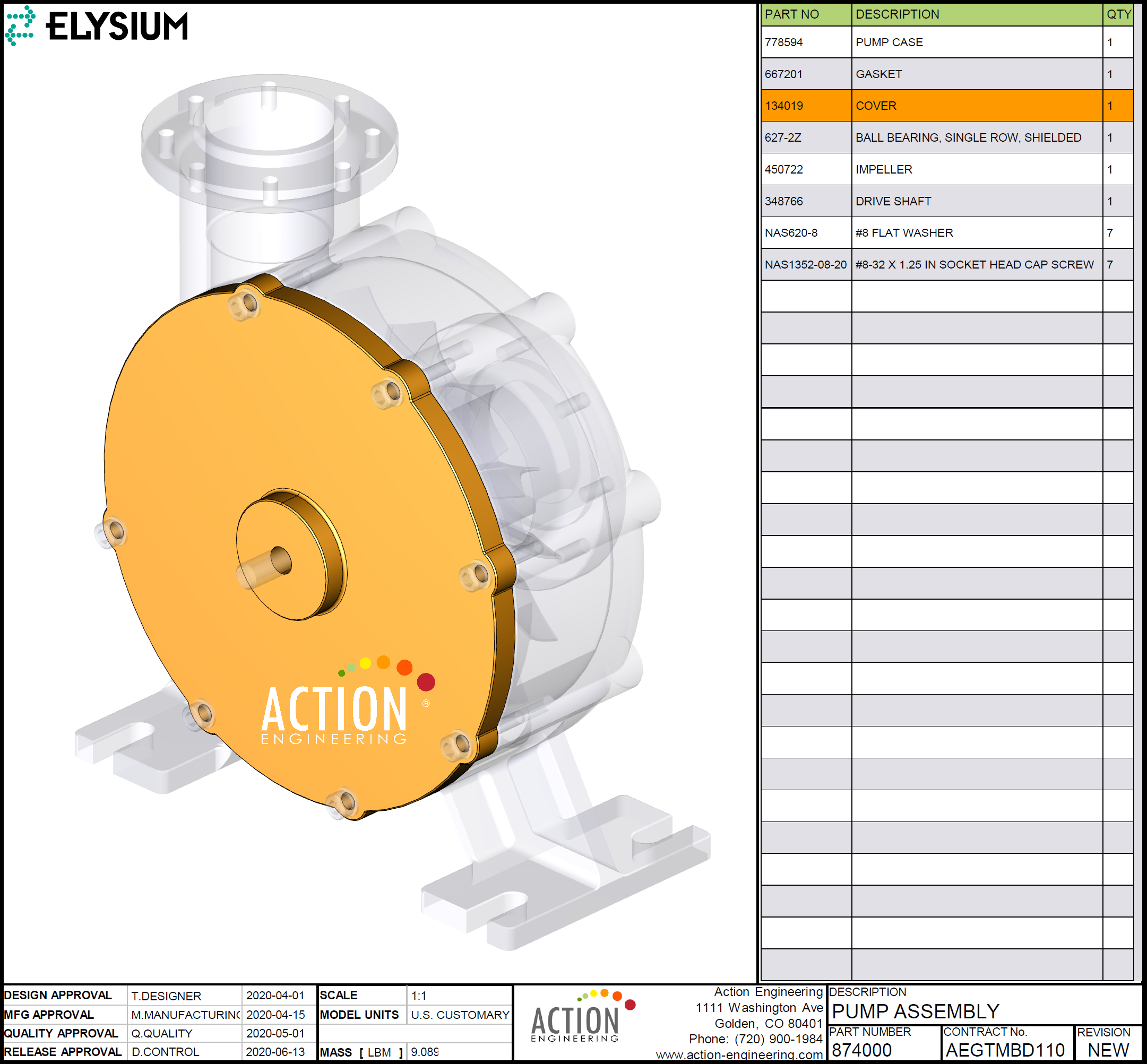 |
| Term: Pattern |  |
| Definition: Two or more features to which a position or profile geometric tolerance is applied and that are grouped by one of the following methods: nX, n COAXIAL HOLES, ALL AROUND, ALL OVER, between A and B (A ? B), from A to B (A ? B), n SURFACES, simultaneous requirements, or INDICATED, where n in these examples represents a number. |
| Term: Pattern-Locating Tolerance Zone Framework | PLTZF |
|
| Definition: The tolerance zone framework that controls the basic relationship between the features in a pattern with that framework constrained in translational and rotational degrees of freedom relative to the referenced datum features. |
| Term: Pedigree | |
| Definition: The record of heritage that proves the veracity of a data item. |
| Definition: A specification that states requirements in terms of the required results with criteria for verifying compliance, but without stating the methods for achieving the required results. A performance specification defines the functional requirements for the item, the environment in which the item operates and interfaces, and the interchangeability characteristics. |
| Definition: A work statement for performance-based acquisitions that describes the required product or service in clear, specific and objective terms with associated measurable outcomes. |
| Term: Perpendicularity | |
| Definition: The condition of a line element, surface, tangent plane, feature’s centerplane, or feature’s axis at an implied or specified basic 90° (perpendicular) angle relative to one or more datum planes or datum axes. |
| Definition: Physical asset configuration is a comprehensive, actionable digital twin. It provides up-to-date information on the composition and structure of a managed item or property. |
| Term: Physical Configuration Audit | PCA |
|
| Definition: Physical examination of the actual configuration of the item being produced. It verifies that the related design documentation matches the item as specified in the contract. The system product baseline is finalized and validated at the PCA. |
| Term: Piece Part | |
| Definition: A single piece not normally subject to disassembly without destruction or impairment of use, such as resistors, transistors, relays, and gears. |
| Term: Position | |
| Definition: The location of one or more features of size relative to one another or to one or more datums. |
| Term: Precise | |
| Definition: Describes a result that has sufficient decision precision. |
| Term: Presentation | |
| Definition: The manner in which information is displayed for use by a human. |
| Term: Presentation State | |
| Definition: A retrievable collection or set of model display elements arranged for formal display to the viewer. |
| Term: Process | |
| Definition: Activity that contributes to realizing a product. |
| Term: Process Data | |
| Definition: Product data that pertains to a process. |
| Term: Process Definition | |
| Definition: Any information that defines a process that contributes to realizing a product. |
| Definition: A dataset that contains process definition. |
| Definition: A system model that encapsulates a process definition. |
| Definition: A specification document (not a drawing) that defines the technical requirements (design performance, environmental, testing, reliability, maintainability, etc.) for an item to be developed by a supplier. |
| Term: Product | |
| Definition: Includes materials, parts, components, subassemblies, assemblies, and equipment. The term product shall also encompass a family of products. |
| Term: Product Characteristic | PC |
|
| Definition: A tolerance or specification applied to a feature or product that requires verification. A characteristic has a local designation identifier(s) and may have a criticality associated with it. |
| Definition: An identifier, which is used as the basis for both a Product Characteristic Reference Identifier (i.e., Tag or UUID), and a Product Characteristic Instance Identifier. |
| Definition: An optional identifier that is concatenated with a Product Characteristic Base Identifier, which uniquely identifies a Product Characteristic Instance Identifier. |
| Definition: An identifier (i.e., Tag or UUID), of an instance of a Product Characteristic Reference Identifier, which combines a Product Characteristic Base Identifier with an optional Product Characteristic Extension Identifier. |
| Definition: A product characteristic tag used as an instance identifier. |
| Definition: An identifier (i.e., Tag or UUID), which references a verification requirement annotation as a Product Characteristic, which contains the Product Characteristic Base identifier. |
| Definition: A product characteristic tag used as a reference identifier. |
| Definition: A characteristic tag used for a product characteristic. |
| Term: Product Data | |
| Definition: A representation of information about a product in a formal manner suitable for communication, interpretation, or processing by human beings or by computers. |
| Term: Product Data Management | PDM |
|
| Definition: A system that manages as-designed data and is the authoritative source for the geometry, attributes, CAD BOM, and revision. | 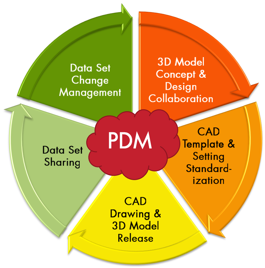 |
| Term: Product Data Management Activities | PDM Activities |
|
| Definition: Activities that interrelate product data. |
| Term: Product Definition | PD |
|
| Definition: Any information that defines the physical or functional requirements of a product, to ensure design intent. |
| Definition: An information system that stores record copies (44 U.S.C.3301) of product definition for their long-term archive and retrieval. |
| Definition: The record of transmittal and supporting procedures that authorize product definition for a lifecycle activity. |
| Term: Product Definition Data | PDD |
|
| Definition: Denotes the totality of product definition elements required to completely define a product. Product definition data includes geometry, topology, relationships, tolerances, attributes, and features necessary to completely define a component part or an assembly of parts for the purpose of design, analysis, manufacture, test, and inspection. |
| Term: Product Definition Data Set | PDDS |
|
| Definition: A collection of one or more data file(s) that discloses, directly or by reference, by means of presentation (e.g., graphic or textual), representation (e.g., semantics or machine readable), or a combination of both, the physical or functional requirements of an item. |
| Definition: A specific product definition data set designation that defines a particular stage of manufacturing and conformance to specification. |
| Definition: A unit of data for which the definition, identification, representation, and permissible values are specified (see Table 3-1). |
| Term: Product Definition Set | |
| Definition: An identified set of product definition that fully defines a product. |
| Definition: A system model that encapsulates a product definition. |
| Term: Product Drawing | |
| Definition: Two-dimensional (2D) flat orthogonal representations of a 3 dimensional object; used to convey design, manufacturing and quality support information related to how an object is to be built, such as dimensions, tolerances, materials, construction notes and processes. Standardized by ASME Y14.5 and Y14.100. |
| Term: Product Information | |
|
Definition: information about a product
Note 1 to entry: Note to entry: In ISO 10303, it is common to describe product information with respect to a specific industrial domain. |
| Term: Product Information Model | PIM |
|
| Definition: The product information model is an information model which provides an abstract description of facts, concepts and instructions about a product, such as a STEP Application reference model or STEP Application interpreted model. (cf NAS9300-003, 3.2.1) |
| Term: Product Lifecycle | |
| Definition: The series of stages through which a product passes during its lifetime. |
| Term: Product Lifecycle Data | |
| Definition: Data that pertains to the product lifecycle. |
| Term: Product Lifecycle Management | PLM |
|
| Definition: A system that manages as-built design information and is the authoritative source for the eBOM, changes, data package, design deviations, and usage. | 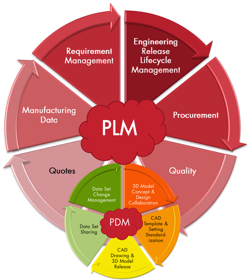 |
| Term: Product Lifecycle Management Software | PLM Software |
|
| Definition: PLM software manages information throughout the entire product lifecycle from ideation, design and manufacture through service and disposal. |
| Term: Product Model | |
| Definition: A digital, 3D representation of an object with precise nominal geometry, attributes, annotations, and fully semantic tolerances that completely and unambiguously defines the product and facilitates model-based manufacturing, inspection, and Product Lifecycle Management. The Product Model is the Manufacturing source and is a model translated and verified from and against the Design Authority model. | |
| Term: Product Requirement | |
| Definition: A requirement that address a product’s purpose, its features, functionalities, and behavior. |
| Term: Product Requirement Association | PRA |
|
| Definition: A characteristic augmentation that optionally relates a product requirement to a characteristic. |
| Definition: A designator for the Product Requirement Association. |
| Term: Product Structure | |
| Definition: A hierarchical list of items that constitute a product. |
| Term: Product and Manufacturing Information | PMI |
|
| Definition: 3D annotations (dimensions and tolerances), metadata, notes and attributes needed to define the product beyond the 3D geometry. |
| Term: Production Management | |
| Definition: The effective use of resources to produce, on schedule, the required number of end units that meet specified quality, performance, and cost. It includes, but is not limited to, industrial resource analysis, producibility assessment, producibility engineering, and planning, production engineering, industrial preparedness planning, post-production planning, and productivity enhancement. |
| Term: Production Readiness | |
| Definition: The state, condition, or preparedness of a system to proceed into production. A system is ready for production when the producibility of the production design and the managerial and physical preparations necessary for initiating and sustaining a viable production effort have progressed to the point where a production commitment can be made without incurring unacceptable risks that will breach thresholds of schedule, performance, cost, or other established criteria. |
| Term: Profile | |
| Definition: An outline of a surface, a shape made up of one or more features, or a two-dimensional element of one or more features. |
| Term: Purchased Item | |
| Definition: A term that encompasses both commercial items and vendor-developed items. |
| Term: QIF Persistent Identifier | QPId |
|
| Definition: a standard universally unique identifier used in QIF |
| Term: Qualification | |
| Definition: The formal process by which a manufacturers product is examined for compliance with the procurement requirements of a source control drawing to approve the manufacturer as a source of supply. |
| Term: Qualified Tooling | |
| Definition: Universal (not part specific) calibrated monitoring and measuring equipment (e.g., go/no go gauges, thread gauges, radius gauges) used to validate product design characteristics, that are uniquely identified and traceable to their calibration records. |
| Term: Quality Activities | |
| Definition: Activities involved in manufacturing verification, testing, inspection, and product acceptance. |
| Term: Quality Assurance | QA |
|
| Definition: A planned and systematic pattern of all actions necessary to provide confidence that adequate technical requirements are established, that products and services conform to established technical requirements, and that satisfactory performance is achieved. |
| Term: Quality Assurance Provisions | QAP |
|
| Definition: Documented requirements, procedures and criteria necessary for demonstrating that products conform to design requirements. |
| Term: Quality Information Framework | QIF |
|
| Definition: An ANSI/DMSC standard for computer-interpretable quality information. |
| Term: Quality Management Systems | QMS |
|
| Definition: A system that manages as-inspected data and is the authoritative source for quality records. |
| Term: Quality Plans | |
| Definition: A set of data that specifies the standards, practices, specifications, resources, and activities required to validate engineering requirements, including compliance objectives, process steps, and responsible parties; typically includes testing, inspection, examination, and audit programs at appropriate stages. |
| Term: Quality of Conformance | |
| Definition: The effectiveness of the design and manufacturing functions in executing the product manufacturing requirements and process specifications while meeting tolerances, process control limits, and target yields for a given product group. |
| Term: Query | |
| Definition: A means of interrogating a digital element or the relationship between digital elements. |
| Term: Record of Authority | |
| Definition: Identifies what data serves as the primary and governing source. Additional data may be derived from this source and additional data may be added to support the manufacture or inspection of the product. |
| Term: Reference | |
| Definition: To invoke associated data by callout on an engineering drawing. Such callouts may be located on the field of the drawing, in a note, in the parts list, or elsewhere on the drawing. |
| Definition: The characteristic (including reference and basic dimensions) that are used for "information only" or to show relationship; these are dimensions without tolerances and refer to other dimensions on the drawing or in the DPD. |
| Term: Reference Data | |
| Definition: Information, including dimensions, that does not govern production or inspection operations. |
| Term: Reference Dimension | |
| Definition: Dimensional information, usually without a tolerance, that is used for reference purposes only. A reference dimension is a repeat of a dimension or is derived from other values shown on the drawing or on related drawings. It is considered auxiliary information and does not govern production or inspection operations. Where a basic dimension is repeated on a drawing, it is not identified as reference. |
| Term: Reference Documents | |
| Definition: Documents referred to in a TDP element, which contain information necessary to meet the information content requirements of that TDP element. |
| Term: Reference Technical Data | |
| Definition: A set of technical data which is provided for information, but is not necessarily validated as accurate, adequate and complete. |
| Term: Referenced Documents | |
| Definition: Design activity standards, drawings, specifications, or other documents referenced on drawings or lists. |
| Term: Regardless of Feature Size | RFS |
|
| Definition: A condition in which a geometric tolerance applies at any increment of size of the unrelated acutal mating envelope (AME) of the feature of size. |
| Term: Regardless of Material Boundary | RMB |
|
| Definition: A condition in which a movable or variable true geometric counterpart progresses from maximum material boundary (MMB) toward least material boundary (LMB) until it makes maximum allowable contact with the extremities of a datum feature(s) to establish a datum. |
| Term: Regular Feature of Size | |
| Definition: One cylindrical surface, a spherical surface, a circular element, or a set of two opposed parallel line elements or opposed parallel surfaces associated with a single directly toleranced dimension. |
| Term: Representation | |
| Definition: The manner in which information is stored for interpretation by a machine. |
| Term: Represented Line Element | |
| Definition: A supplemental geometry line or curve segment indicating the orientation of a direction dependent tolerance. |
| Definition: A first level refinement of one or more capability requirements identified in an Information Systems - Initial Capabilities Document (IS-ICD) or Information Systems - Capability Development Document (IS-CDD), and is co-developed by the operational user (or representative) and the program office. The RDP (or equivalent) identifies the Key Performance Parameters (KPPs), including the Net-Ready KPP, Key System Attributes (KSAs), and Additional Performance Attributes (APAs) necessary to scope and cost implementation of a capability solution. The RDP (or equivalent) may also identify non-material changes that need to be implemented to fully realize the IS capability solution. The RDP (or equivalent) is approved by the delegated oversight authority listed in the IS-ICD or IS-CDD. |
| Term: Requirements Management | |
| Definition: Gathering and managing user, business, technical, and functional requirements within a product development project. Four types of requirements must be considered: user requirements, business requirements, technical requirements, and process or operational requirements. |
| Term: Resolved Dimension | |
| Definition: A model value that is rounded off to the number of decimal places required for the design. | 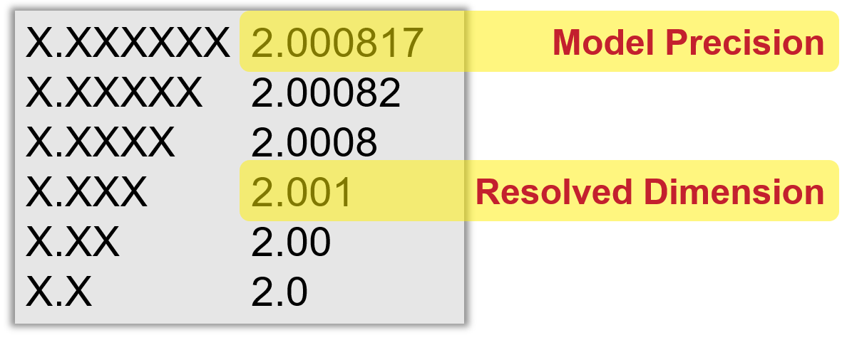 |
| Term: Restrained | |
| Definition: The condition in which externally induced forces in addition to gravity are applied to a part. |
| Term: Resultant Condition | |
| Definition: The single worst-case boundary generated by the collective effects of a feature of size’s specified MMC or LMC, the geometric tolerance for that material condition, the size tolerance, and the additional geometric tolerance derived from the feature’s departure from its specified material condition. |
| Definition: A document recognized as the authority for making a change to a drawing or associated documentation. Revision authorization documents are frequently identified by terms such as alteration notice (AN), advance drawing change notice (ADCN), change in design (CID), drawing change notice (DCN), engineering change notice (ECN), engineering change order (ECO), engineering notice (EN), engineering order (EO), or notice of revision (NOR) (see ASME Y14.35). |
| Term: Robust Design | |
| Definition: The design of a system such that its performance is insensitive to variations in manufacturing tolerances, or its operational environment (including maintenance, transportation, and storage), or to component drift as a result of aging. |
| Term: Roughness | |
| Definition: The finer spaced irregularities of the surface texture that usually result from the inherent action of the production process or material condition. |
| Term: Runout | |
| Definition: A general term that applies to both circular and total runout. |
| Term: SMRL | STEP modules and resource library |
|
| Definition: collection of application modules, business object models, and integrated resources intended to support one or more application protocols |
| Term: STEP | |
| Definition: Standard for The Exchange of Product model data, the common name for ISO 10303. |
| Term: Saved View | |
| Definition: A stored and retrievable specific orientation and a magnification factor of a model or design model and may be a view within a model or a view generated from the model and placed in a drawing graphic sheet (ASME Y14.3). |
| Term: Security Markings | |
| Definition: Security markings are permanently displayed markings on the model. These markings are not obscured by the model and are visible regardless of the layer state, combined state, or visibility state of the model. You can designate notes and symbols that are flat-to-screen, standalone, and unattached, as security markings. |
| Term: Segment | |
| Definition: A grouping of elements that are closely related and often physically interface. These include configuration items (CIs) produced by several contractors and integrated by one contractor. |
| Term: Selected Item Drawing | |
| Definition: A product definition data depicting an existing standard or vendor-developed item with further required selection or restriction of the item for fit, tolerance, performance, or reliability within the range or limits prescribed for the item. Although the existing item is not physically modified, by virtue of the selection technique employed it is demonstratively different from those identified on the document from which the selection is made and, therefore, the existing item is not interchangeable with the selected item. When so restricted, the existing item is re-identified with a new part number from the authoring design activity replacing the original part number. |
| Term: Semantic Annotation | |
| Definition: The process of adding structured, machine-readable data with geometric model elements so that it is digitally consumable |
| Term: Semantic PMI | |
| Definition: PMI that associates to digital elements. |
| Term: Separate Parts List | |
| Definition: A parts list prepared as a document separate from the engineering drawing to which it is associated, and one that may be revised independently of the drawing. |
| Term: Service Activities | |
| Definition: Activity involved in servicing products. |
| Term: Service Bill of Material | SBOM |
|
| Definition: The Service bill of material is the structure of the product, initially as it was built (the MBOM), but then modified as the product is installed and serviced in operation. |
| Term: Service Characteristic | SC |
|
| Definition: A characteristic, which is created to identify a service or maintenance requirement for the sustainment of a product or of a feature of a product. |
| Term: Simplified Drawing | |
| Definition: A drawing with minimal views and dimensional characteristics that relies on the model to provide complete part definition. |
| Term: Simulated Datum | |
| Definition: A point, axis, line, or plane (or combination thereof) derived from a datum feature simulator. |
| Term: Simulation & Analysis | |
| Definition: Modeling, exercising, and analyzing a design’s behavior without physically building the design. The simulator and simulation model have all the necessary attributes of the physical design. |
| Definition: A concept that envisions greater and more integrated use of Modeling and Simulation (M&S) in the acquisition process. DoD and industry would be enabled by robust, collaborative use of simulation technology that is integrated across acquisition programs and phases. |
| Term: Simultaneous Requirement | |
| Definition: The condition in which two or more geometric tolerances apply as a single pattern or part requirement. |
| Term: Skeleton Model | |
| Definition: A model that contains a sketch, surface and/or solid model used to facilitate top-down modeling, by allowing multiple users to access interface geometry from a single model. When the skeleton model is changed, those changes are proliferated to any associated geometry in other models that use the skeleton reference geometry. A skeleton model will always have ZERO MASS, as it is a reference-only model. | 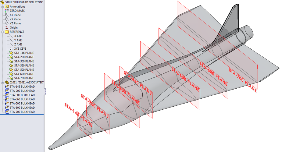 |
| Term: Sketch | |
| Definition: A two-dimensional profile used to create a CAD feature. May or may not be constrained to a part's coordinate system, planes, or axis. |
| Term: Small Sized Assemblies | |
| Definition: An assembly which has a total of all components (Company, Industry (including fasteners), Supplier), including all the instances (not unique parts) in the assembly are less than 200 parts. |
| Term: Smart Manufacturing | |
| Definition: An approach to manufacturing that leverages 3D data and factory machinery with sensors to monitor and improve the production process and performance. |
| Term: Solid Model | |
| Definition: A mathematically accurate 3D representation of an object. A solid model has thickness, and when calculated, results in numeric values for mass, center of mass, and Moments of Inertia (MOI). A solid model is not a collection of disconnected, unstitched surfaces. | 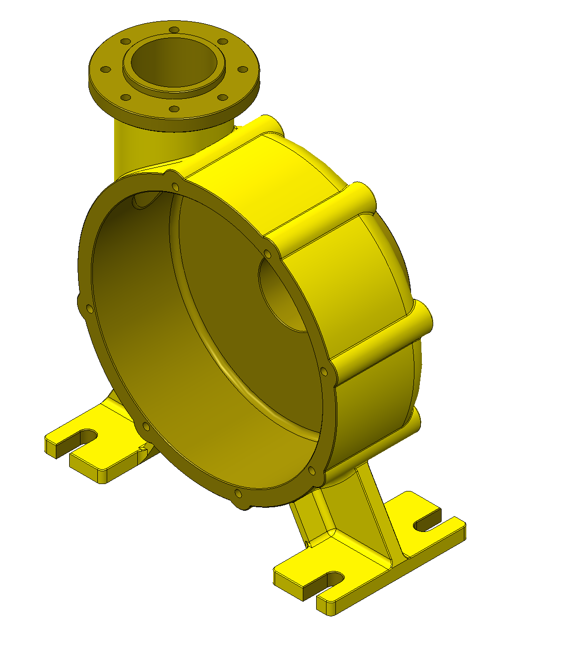 |
| Term: Source | |
| Definition: An artifact that is transformed into a derivative. |
| Term: Source Control Drawing | SOCD |
|
| Definition: A product definition data that depicts the requirements for an existing supplier item or a developed supplier item that is required to be approved and qualified for use and that exclusively provides the performance, installation and interchangeable characteristics required for one or more specific critical applications. The specific applications are stated on the drawing. The item is reidentified with a new part number from the authoring design activity. |
| Term: Source Model | |
| Definition: The model from which a derivative is obtained. |
| Term: Source of Truth | |
| Definition: The single authoritative source that contains the original information item. |
| Term: Spatial Model | |
| Definition: A model that represents geometric and/or spatial relationships. |
| Term: Special Process | |
| Definition: Any processes for production and service provision where the resulting output cannot be verified by subsequent monitoring or measurement and, as a consequence, deficiencies become apparent only after the product is in use or the service has been delivered. |
| Term: Specification | |
| Definition: A document that describes essential technical requirements for material and the criteria for determining whether those requirements are met. |
| Term: Standard | |
| Definition: A document that establishes technical criteria, methods, processes, and practices. | 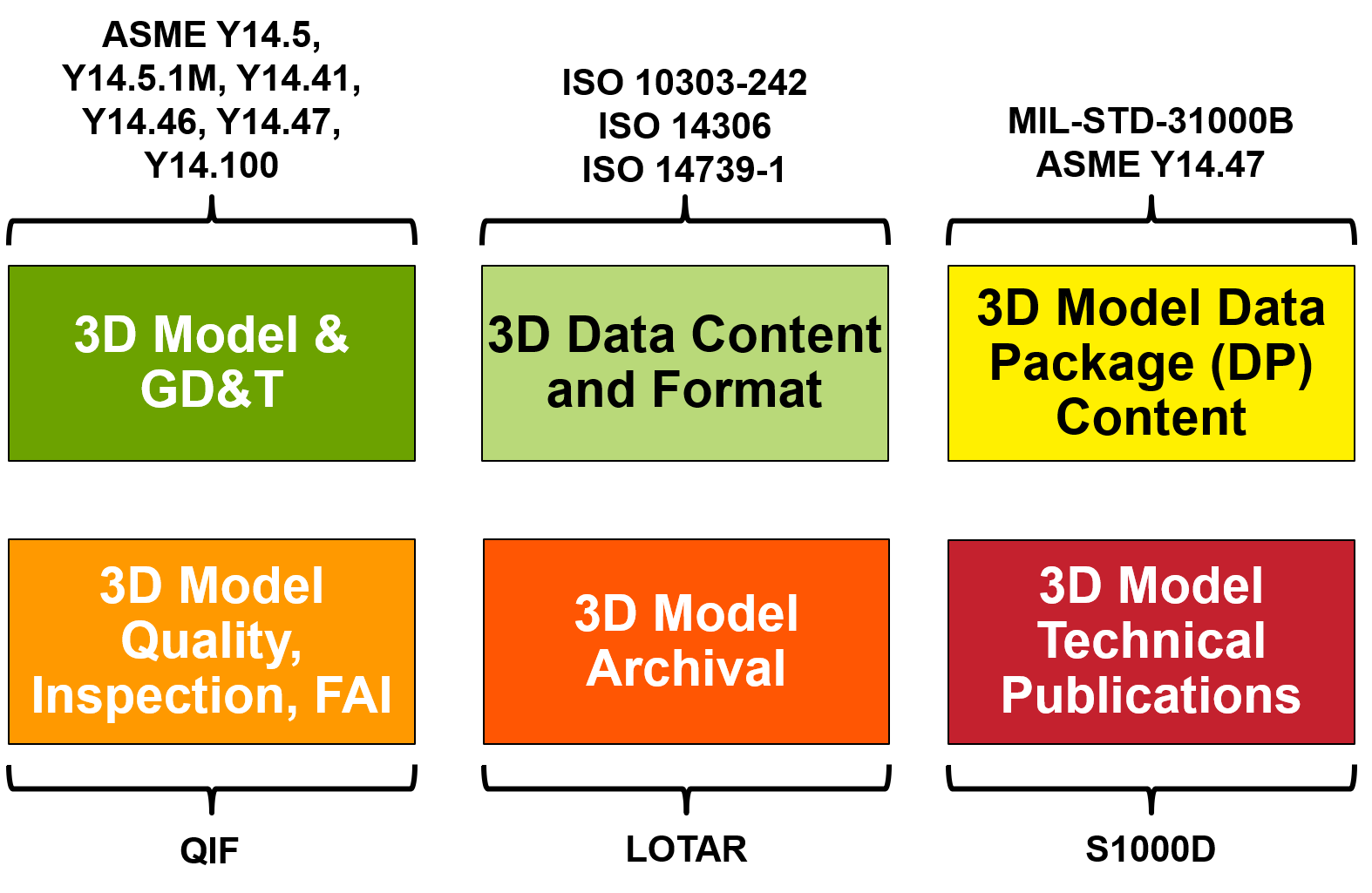 |
| Term: Standard Catalogue Item | |
| Definition: A part or material that conforms to an established industry or national authority published specification, having all characteristics identified by text description or industry/national/military standard drawing. |
| Term: Standard Data | |
| Definition: Data that have been approved formally in accordance with the organization’s data standardization procedures. |
| Term: Standardization | |
| Definition: The process of developing and agreeing on (by consensus or decision) uniform engineering criteria for products, processes, practices, and methods for achieving compatibility, interoperability, interchangeability, or commonality of material. |
| Term: Standardization Document | |
| Definition: A document developed for the purpose of standardizing items, materials, processes, or procedures. |
| Term: Start Component | |
| Definition: A standard component that can be used as a template for the creation of new parts or assemblies. |
| Term: Start-Process Model | |
| Definition: The initial process model for a process definition. |
| Term: Statistical Tolerancing | |
| Definition: The assigning of tolerances to related components of an assembly on the basis of sound statistics (e.g., the assembly tolerance is equal to the square root of the sum of the squares of the individual tolerances). |
| Term: Straightness | |
| Definition: The condition in which an element of a surface, or a derived median line, is a straight line. |
| Term: Subassembly | |
| Definition: Two or more parts that form a portion of an assembly or a unit replaceable as a whole but having a part or parts that are individually replaceable - e.g., gun mount stand, window sash, recoil mechanism, floating piston, telephone dial, Intermediate Frequency (IF) strip, terminal board with mounted parts. | 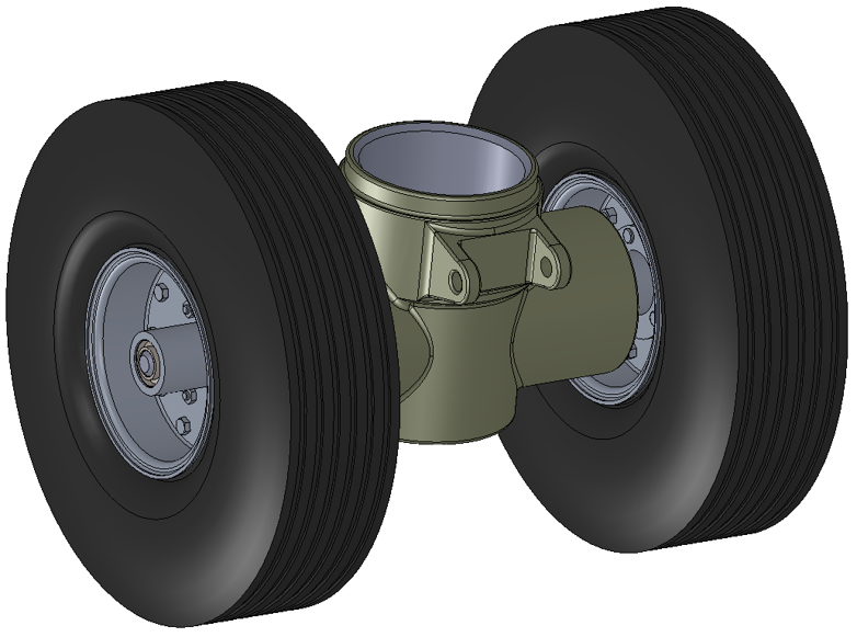 |
| Term: Supplemental Dataset | |
| Definition: Data elements included in product definition data to communicate design requirements but not intended to represent an item. |
| Term: Supplemental Geometry | |
| Definition: Geometric elements included in product definition data to communicate design requirements but not intended to represent an item. | 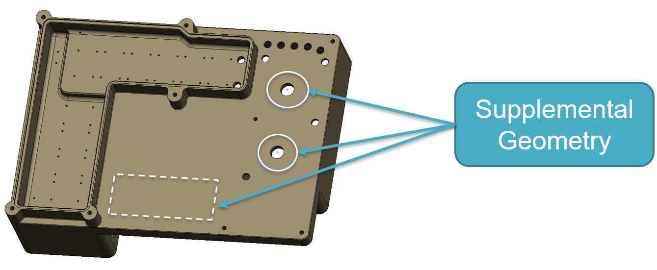 |
| Definition: Deliverable data products used by the procuring activity to better acquire and support the end product defined by the TDP. When supplementary technical data is required, it shall be delivered in accordance with the contract. |
| Term: Support | |
| Definition: Structure separate from the part geometry that is created in order to provide a base and anchor for the part during the building process. |
| Term: Support Model | |
| Definition: A digital representation of a thing provided as complementary to a primary artifact. |
| Term: Surface | |
| Definition: A mathematical representation of a flat or curved bounded space having length and width but no thickness. A surface may consist of multiple surface patches adjacent on all internal edges. |
| Term: Surface Model | |
| Definition: A mathematical or digital representation of an object as a set of planar or curved surfaces, or both, that may or may not represent a closed volume. |
| Term: Surface Texture | |
| Definition: The composite of certain deviations that are typical of the real surface. Surface texture includes roughness and waviness. |
| Definition: Those parts that are mirror images of each other. |
| Term: System | |
| Definition: A composite of equipment, skills, and techniques capable of performing or supporting an operational role or both. A complete system includes all equipment, related facilities, material, software, services, and personnel required for its operation and support to the degree that it can be considered a self- sufficient unit in its intended operational environment. |
| Term: System Model | |
| Definition: A logical model of interconnected structures, behaviors, parametrics, and requirements of a system. |
| Definition: Activities for system engineering of systems. |
| Term: TDP Element | |
| Definition: A data product that is an actual component of the TDP. A TDP element provides all or part of the information necessary to define the item being documented by the TDP. All TDP elements taken collectively provide a complete Technical Data Package. |
| Term: TDP Level | |
| Definition: TDP levels provide for a natural progression of a design from its inception to production. A particular TDP level may be ordered to define a conceptual design, a developmental prototype or limited production design, or full scale production of the item by the original design activity or any other capable manufacturer. TDPs consist of one of three Levels: (1) Conceptual Level (2) Developmental Level (3) Production Level. |
| Term: TDP Metadata | |
| Definition: Metadata consist of data from and about TDP elements and is used by the procuring activity to manage the TDP development process and to better acquire and support the end product defined by the TDP. When metadata is required, it shall be delivered in accordance with the contract. |
| Term: TDP Type | |
| Definition: TDP type describes the form and format of the data. The following types can be imposed by the contract: Type 2D (2-Dimensional (2D) Technical Data Package) or Type 3D (3-Dimensional (3D) Technical Data Package). |
| Term: Tag | |
| Definition: A digital element identifier used as a human-readable identifier, unique within a local context. |
| Term: Tailoring | |
| Definition: The process by which the requirements of specifications, standards, and related documents are modified to be suitable for a specific application or project (see EIA-632). |
| Term: Tangent Plane | |
| Definition: A plane that contacts the high point or points of the specified surface. |
| Term: Technical Authority | TA |
|
| Definition: Entity responsible to establish, approve, and assess conformance to technical, safety, and certification requirements and policy for both products and processes. The term TA term can refer to the overall TA for a program or the TA for a specific engineering or technical discipline or design consideration. For example, the Federal Aviation Agency is the TA for civilian aircraft airworthiness and the USAF Technical Airworthiness Authority is the TA for Air Force aircraft airworthiness. |
| Term: Technical Coherence | |
| Definition: The logical traceability of the evolution of a system’s data and models, decisions, and solutions throughout the lifecycle. |
| Term: Technical Data | |
| Definition: Recorded information of scientific or technical nature, regardless of form or character (such as equipment technical manuals and engineering drawings), [such as] engineering data, specifications, standards and Data Item Descriptions (DID). Data rights, data delivery, proprietary data use, and data management needs are included in technical data as are as maintained bills of material and system configuration by individual system identification code. Technical data does not include computer software or financial, administrative, cost or pricing, or management data or other information incidental to contract administration. |
| Term: Technical Data Package | TDP |
|
| Definition: The authoritative technical description of an item. This technical description supports the acquisition, production, inspection, engineering, and logistics support of the item. | 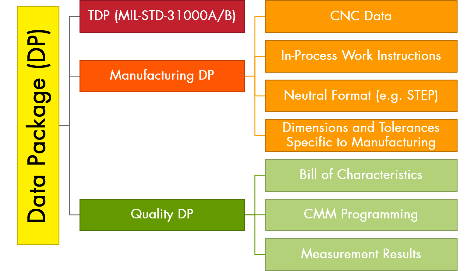 |
| Definition: A data product that is used to monitor and control the development and maintenance of the TDP. A TDP data management product contains information about the TDP rather than the item being documented. |
| Term: Technical Data Package List | TDPL |
|
| Definition: An index of all documents contained in a technical data package established at a point in time. TDPLs contain a list of all specifications, engineering design data, (i.e. drawings, models, 3Di viewables, etc.), QAPs, inspection documents, packaging documents, or other documents which comprise the TDP listed by nomenclature, document CAGE code, document number, distribution statement, revision, and date. |
| Term: Technical Performance Measure | TPM |
|
| Definition: Quantifiable attribute of both the system’s development processes and status, as well as the system’s product performance and maturity. TPMs are collected to provide information to Program Managers and Systems Engineers at routine intervals for decision making. |
| Term: Technology Readiness Level | TRL |
|
| Definition: One level on a scale of 1 to 9, e.g., TRL 3, signifying technology readiness pioneered by the National Aeronautics and Space Administration (NASA), adapted by the Air Force Research Laboratory (AFRL), and adopted by the Department of Defense as a method of estimating technology maturity during the acquisition process. The lower the level of the technology at the time it is included in a product development program, the higher the risk that it will cause problems in subsequent product development. |
| Term: Test Coupon | |
| Definition: A test specimen defined by a standard, produced for the purpose of obtaining test results that comply with the requirements of the applicable product standard, sometimes built at the same time as the part for additive manufacturing processes. |
| Term: The Four Parts of MBD | |
|
Definition: Model-Based Definition (MBD) is a model with PMI (Product Manufacturing Information) and consisting of:
1. the 3D geometry (serves as the basic dimensions) 2. the annotations (displayed notes, dimensions and tolerances or GD&T) 3. the attributes (metadata, key characteristics, and queried data) 4. the presentation states (saved views, presentation organization)
|
| Definition: Supplemental geometry, explicitly defined in the design model and similar to true profile, that may be used to control the form, size, orientation, or location of a functional collection of points, lines, surfaces, or any combination thereof. |
| Term: Tolerance | |
| Definition: The total amount a dimension or feature is permitted to vary. The tolerance is the difference between the maximum and minimum limits. |
| Term: Tolerance Stack-Up | |
| Definition: The cumulative tolerance that occurs when Creo Parametric uses a series of dimensions with tolerances to dimension a certain feature in a part or an assembly member. |
| Term: Topology Optimization | |
| Definition: A subtractive generative design process that refines an existing 3D geometric model. |
| Term: Total Runout | |
| Definition: The condition in which all elements of a surface or tangent plane are at zero variation relative to a datum axis or axis of rotation established from the datum reference frame. |
| Term: Traceability | |
| Definition: The ability to traverse the digital thread. |
| Term: Track Path | |
| Definition: The additive manufacturing machine-material interface path through space for producing the desired geometry of the layer. |
| Term: Transition Region | |
| Definition: A bounded region where gradient control applies. |
| Term: Translation | |
| Definition: The conversion of a 3D CAD model from one format to another. |
| Definition: The theoretically perfect boundary used to establish a datum from a specified datum feature. NOTE: This term is only applicable to datums. |
| Term: True Position | |
| Definition: The theoretically exact location of a feature of size, as established by basic dimensions. |
| Term: True Profile | |
| Definition: The profile defined by basic radii, basic angular dimensions, basic coordinate dimensions, basic dimension of size, undimensioned drawings, formulas, or mathematical data, including design models. |
| Term: Trusted | |
| Definition: Regarded with confidence by a consumer, and concurrently being certified, authorized, and authenticated. | 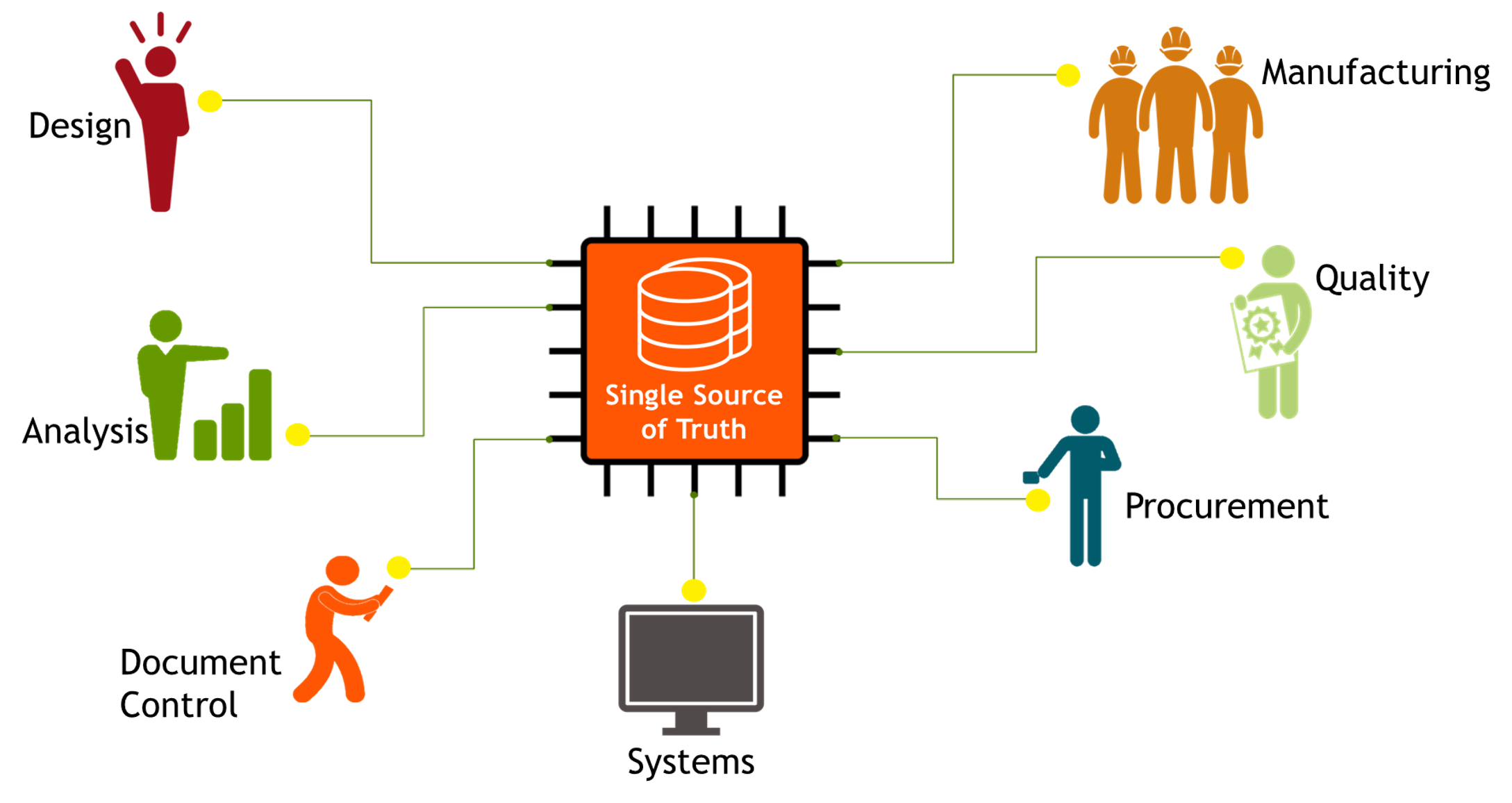 |
| Term: Trusted Data | |
| Definition: Facts given for storage or processing that are regarded with confidence by a consumer, and concurrently being certified, authorized, and authenticated. |
| Term: Type 2D TDP | |
|
Definition: 2-Dimensional Technical Data Package (2D TDP).
A 2D TDP is based on 2 dimensional engineering drawings in accordance with ASME Y14.100 series standards |
| Term: Type 3D TDP | |
|
Definition: 3-Dimensional (3D) Technical Data Package.
Type 3D will include one or more of the below as specified in the contract and TDP Option Selection Worksheet: (1) 3D native models. (2) 2D drawings derived from the 3D native models. (3) 3Di pdf viewable data derived from the 3D native models. (4) Neutral files derived from the 3D native models. |
| Term: Unambiguous | |
| Definition: Resolves to the intended interpretation. |
| Definition: A tolerance that permits unequal amounts of variation in both directions from the specified dimension or true profile. |
| Term: Uniform Tolerance Zone | |
| Definition: A constant distance between two boundaries equally or unequally disposed about the true profile or entirely disposed on one side of the true profile. |
| Term: Unilateral Tolerance | |
| Definition: A tolerance in which variation is permitted in one direction from the specified dimension or true profile. |
| Term: Unit | |
| Definition: An assembly or any combination of parts, subassemblies, and assemblies mounted together normally capable of independent operation in a variety of situations (e.g., hydraulic jack, electric motor, electronic power supply, internal combustion engine, electric generator, radio receiver). NOTE: The size of an item is a consideration in some cases. An electric motor for a clock may be considered as a part because it is not normally subject to disassembly. |
| Term: Universally Unique Identifier | UUID |
|
| Definition: A digital element identifier used as a persistent machine-readable universally unique identifier. The UUID should be generated according to the ISO/IEC 9834-8 standard. |
| Term: V&V | |
| Definition: Acronym For: Verification and Validation | 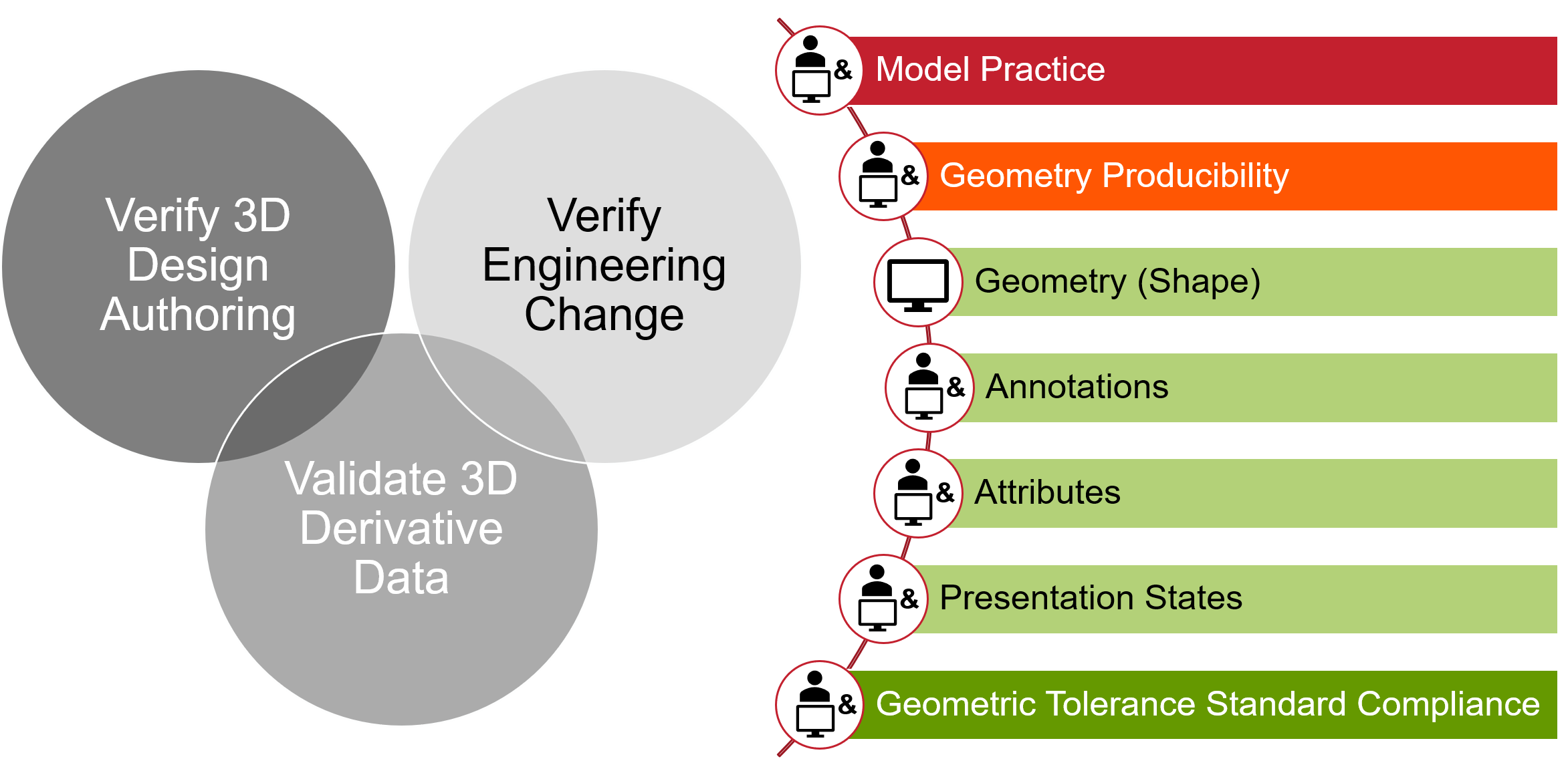 |
| Term: Validated | |
| Definition: Assured to satisfy intent. |
| Term: Validation | |
| Definition: An activity that assures that a product satisfies intent. |
| Term: Validation Properties | |
| Definition: Information calculated from a model or document whose invariance is used to validate the content after recovery, and so to demonstrate that the key characteristics are unchanged. For example, the volume of a solid in a CAD file. |
| Term: Vendor | |
| Definition: A source from whom a purchased item is obtained. |
| Definition: A product definition data depicting the requirements for an existing supplier item or a developed supplier item that does not require item qualification in the use of a critical application but does impose specific engineering design requirements and acceptance criteria to the supplier. The item is not reidentified with a new part number and retains the original supplier item identification. (Formally called vendor item drawing or specification control drawing). |
| Term: Vendor-Developed Item | |
| Definition: A specialized version of a vendor’s general product line which is not normally stocked as an off-the-shelf item but is procurable on order. |
| Term: Verification | |
| Definition: An activity that assures that a product satisfies requirements. |
| Definition: A Product Characteristic, which is supplemented by a Verification Plan Requirement augmentation. |
| Definition: A characteristic augmentation that optionally relates a verification plan requirement to the characteristic. |
| Definition: A designator for the Verification Plan Requirement. |
| Term: Verification Requirement | |
| Definition: A requirement (e.g., tolerance, specification) applied to a part feature or product, which requires verification to assure product acceptance. |
| Term: Verified | |
| Definition: Assured to satisfy requirements. |
| Term: Viewable CAD Data | |
| Definition: CAD data which is derived from the native format and converted into a format which can be displayed by a widely available software and for purposes of defining design intent in a human readable format (e.g. 3Di PDF). In general, viewable CAD data cannot serve as master technical data but may serve as either reference or authoritative technical data. | |
| Term: Virtual Condition | VC |
|
| Definition: A constant boundary generated by the collective effects of a considered feature of size’s specified MMC or LMC and the geometric tolerance for that material condition. |
| Term: Waviness | |
| Definition: The more widely spaced component of the surface texture. Waviness may be caused by such factors as machine or workpiece deflections, vibration, and chatter. Roughness may be considered as superimposed on a wavy surface. |
| Term: Work Instruction | |
| Definition: information that provides instructions about actions or action methods to be used in executing a measurement plan |
| Term: Work Package | |
| Definition: A group of related items that do not make up a complete assembly, with instructions for installing the items in a major assembly structure (e.g., a power supply and mounting hardware with instructions for installing them in a telecommunications satellite structure). |
| Definition: The model used for creation and modification by the native application; it corresponds generally to the design stage of the Product Model; this Working Form is often in the native format of the COTS application. |
| Term: xBOM | |
| Definition: A type of BOM used for a given lifecycle activity. |
| Term: xModel | |
| Definition: A model used for a given lifecycle activity. |