______ END ______
| PTC - PTC Fundamentals, MBD, and Assembly Glossaries | Reference | 2023 |
| Term: Annotation Element |  |
| Definition: An entity in the CAD model that contains an annotation, such as a dimension or a geometric tolerance. |
| Term: Annotation Plane | |
| Definition: A conceptual plane containing annotation. |
| Term: Assembly | |
| Definition: A number of parts or combination thereof that are joined together to perform a specific function and subject to disassembly without degradation of any of the parts (e.g., power shovel-front, fan assembly, audio- frequency amplifier). NOTE: The distinction between an assembly and a subassembly is determined by individual application. An assembly in one instance may be a subassembly in another instance where it forms a portion of a higher assembly. | 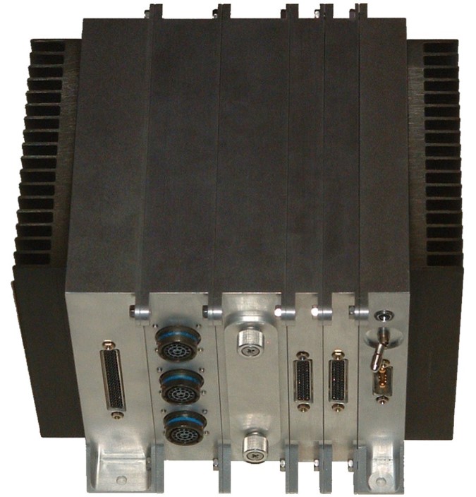 |
| Term: Bulk Items | |
| Definition: Those constituents of an assembly or part (such as oil, wax, solder, cement, ink, damping fluid, grease, flux, welding rod, twine, or chain) that satisfy one or more of the following criteria: the quantity required cannot readily be predetermined; the physical nature of the material is such that it is not adaptable to pictorial representation; the finished size is obtainable through use of such tools as shears, pliers, or knives, without further machining operation; and the final configuration is such that it can be described in writing without the necessity of pictorial representation. |
| Term: Component | |
| Definition: A part or subassembly model that is assembled into an assembly or subassembly model. | 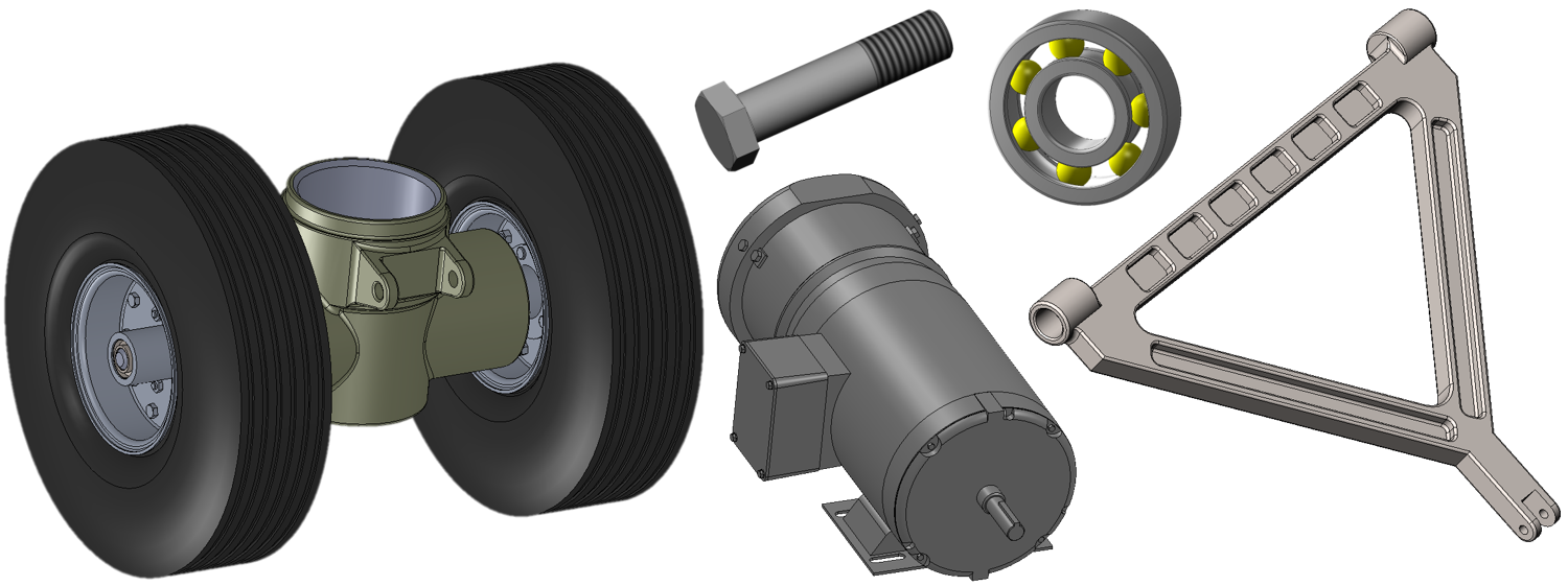 |
| Term: Driven Dimension | |
| Definition: Dimensions in a drawing file derived from the 3D model. Driven dimensions reflect changes to part or assembly geometry, but you cannot modify their values in the drawing. The association is one-way; from the model to the drawing. |
| Term: Driving Dimension | |
| Definition: A dimension that when modified in the drawing is also modified in the 3D model from which it originated. |
| Term: Envelope | |
| Definition: A part created to represent a predetermined set of components in an assembly. The envelope uses simple geometry to reduce system memory usage and looks similar to the components it represents. |
| Term: Family Tables | |
| Definition: A collection of parts (or assemblies or features) that are essentially similar, but deviate slightly in one or two aspects, such as size or detail features. For example, wood screws come in various sizes, but they all look alike and perform the same function. Thus, it is useful to think of them as a family of parts. Parts in Family Tables are also known as table-driven parts. |
| Term: Feature | |
| Definition: A physical portion of a part (such as a surface, pin outside diameter, hole, or slot) or its representation on drawings, models, or digital data files. |
| Term: Instance | |
| Definition: Each instantiation of a component is called an instance. It may appear that the part model (component) is copied several times within a single assembly, yet the other representations are merely visualizations of the source data. | 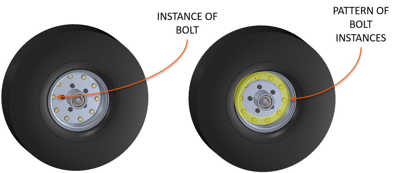 |
| Term: Model Tree | |
| Definition: A Model Tree is a list of every feature in a part file including the datums and coordinate system. Creo Parametric displays the model structure in a hierarchical tree format with the current part or assembly as root object at the top of the tree. The subordinate parts or features are displayed below the root object. |
| Term: Parameter | |
| Definition: A variable in the CAD system. |
| Term: Parametric | |
| Definition: A term used to classify curves for which the path is described by a mathematical function rather than a set of coordinates. A parameter within the function (often specified as u or v) is varied from 0 to 1 to define all the coordinate points along the curve. |
| Term: Parametric Assembly | |
| Definition: An assembly in which a component position updates as the referenced components move or change. |
| Term: Reference Dimension | |
| Definition: Dimensional information, usually without a tolerance, that is used for reference purposes only. A reference dimension is a repeat of a dimension or is derived from other values shown on the drawing or on related drawings. It is considered auxiliary information and does not govern production or inspection operations. Where a basic dimension is repeated on a drawing, it is not identified as reference. |
| Term: Security Markings | |
| Definition: Security markings are permanently displayed markings on the model. These markings are not obscured by the model and are visible regardless of the layer state, combined state, or visibility state of the model. You can designate notes and symbols that are flat-to-screen, standalone, and unattached, as security markings. |
| Term: Skeleton Model | |
| Definition: A model that contains a sketch, surface and/or solid model used to facilitate top-down modeling, by allowing multiple users to access interface geometry from a single model. When the skeleton model is changed, those changes are proliferated to any associated geometry in other models that use the skeleton reference geometry. A skeleton model will always have ZERO MASS, as it is a reference-only model. | 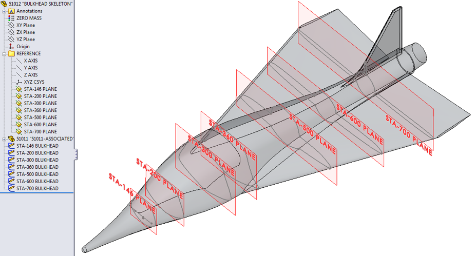 |
| Term: Start Component | |
| Definition: A standard component that can be used as a template for the creation of new parts or assemblies. |
| Term: Subassembly | |
| Definition: Two or more parts that form a portion of an assembly or a unit replaceable as a whole but having a part or parts that are individually replaceable - e.g., gun mount stand, window sash, recoil mechanism, floating piston, telephone dial, Intermediate Frequency (IF) strip, terminal board with mounted parts. |  |
| Term: Tolerance Stack-Up | |
| Definition: The cumulative tolerance that occurs when Creo Parametric uses a series of dimensions with tolerances to dimension a certain feature in a part or an assembly member. |