______ END ______
| ASME Y14.41 - Digital Product Definition Data Practices | Reference | 2019 |
| Term: Annotated Model |  |
| Definition: A combination of model, annotation, and attributes that describe a product. |
| Term: Annotation | |
| Definition: Visible dimensions, tolerances, notes, text, or symbols. |  |
| Term: Annotation Plane | |
| Definition: A conceptual plane containing annotation. |
| Term: Assembly Model | |
| Definition: An annotated model in which the product described is an assembly of two or more items. |  |
| Term: Associated Entity | |
| Definition: The portion of a product definition data to which annotation or attribute(s) pertain. |
| Term: Associated Group | |
| Definition: A user-defined set of related digital elements. |
| Term: Associativity | |
| Definition: The established relationship between digital elements. |
| Term: Attribute | |
| Definition: A dimension, tolerance, note, text, or symbol required to complete the product definition or feature of the product that is not visible but available upon interrogation of the annotated model. |  |
| Term: Classification Code | |
|
Definition: A designation assigned to product definition data that defines what product definition elements are included within the drawing graphic sheet, data set, or both.
NOTE: A drawing graphic sheet may be in either physical or electronic format. |
| Term: Classification Code 1 | |
|
Definition: Drawing Graphic Sheet With Optional Data Set
Identifies that product definition elements are located on the drawing graphic sheet. |
| Term: Classification Code 2 | |
|
Definition: Data Set With Model and Drawing Graphics Sheet
Identifies that product definition elements are located on a drawing graphic sheet. A computer is used as a tool to prepare the drawing graphics sheet and model. Product definition elements are located in the digital data and drawing graphic sheet.
|
| Term: Classification Code 3 | |
|
Definition: Data Set With Model and Simplified Drawing Graphics Sheet
Identifies a model with a simplified drawing graphic sheet used to expedite communication of common part features and to define nongeometric part definitions. |
| Term: Classification Code 4 | |
|
Definition: Data Set With Annotated Model and Drawing Graphics Sheet
Identifies that all product definition elements are located in both the digital data and drawing graphic sheet. |
| Term: Classification Code 5 | |
|
Definition: Data Set With Annotated Model and No Drawing Graphic Sheet
Identifies that all product definition elements are located in the data set. No drawing graphic sheet exists.
|
| Term: Coordinate System | |
| Definition: A representation of a system to determine the position of geometric elements in space, e.g., Cartesian coordinate system. |  |
| Term: Data | |
| Definition: Information represented in a formal manner suitable for communication, interpretation, or processing by human beings or computers. |
| Term: Derivative | |
| Definition: Data duplicated or extracted from the original. A copy of a derivative is also a derivative. |
| Term: Design Model | |
| Definition: The portion of the data set that contains model geometry and supplemental geometry. |
| Term: Digital Element | |
| Definition: Geometric element, feature, group of features, annotation, associated group, or attribute that exists in a data set. |
| Definition: A label or name used to specify a unique digital element. |
| Term: Geometric Element | |
| Definition: A discrete entity (e.g., point, line, curve, plane, surface, solid, volume, vector, coordinate system) used in a digital data set to represent or present physical features of the product definition. |
| Term: Installation Model | |
| Definition: A model in which the product described is an installation, showing parts or assemblies and a partial or complete representation of the installation site. |
| Term: Management Data | |
| Definition: The data required for the release, control, and storage of product definition data as well as other relevant engineering data. |
| Term: Model | |
| Definition: The portion of the data set that contains model geometry and supplemental geometry. | 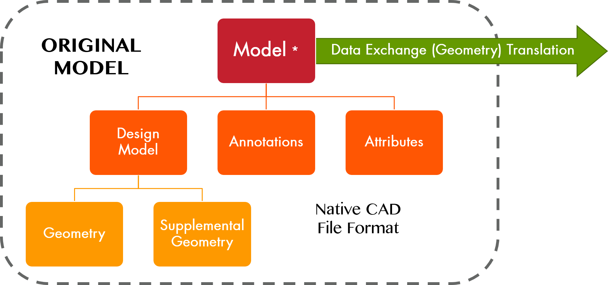 |
| Term: Model Geometry | |
| Definition: Geometric elements used to represent the definition of an item. |
| Term: Model Value | |
| Definition: The numerical value derived by interrogating the model that quantifies the form and spatial relationships of the geometry composing a model, or assembly of models, to the precision [number of decimal places] of the computer system. |
| Term: Product Definition Data | PDD |
|
| Definition: Denotes the totality of product definition elements required to completely define a product. Product definition data includes geometry, topology, relationships, tolerances, attributes, and features necessary to completely define a component part or an assembly of parts for the purpose of design, analysis, manufacture, test, and inspection. |
| Term: Product Definition Data Set | PDDS |
|
| Definition: A collection of one or more data file(s) that discloses, directly or by reference, by means of presentation (e.g., graphic or textual), representation (e.g., semantics or machine readable), or a combination of both, the physical or functional requirements of an item. |
| Term: Query | |
| Definition: A means of interrogating a digital element or the relationship between digital elements. |
| Term: Represented Line Element | |
| Definition: A supplemental geometry line or curve segment indicating the orientation of a direction dependent tolerance. |
| Term: Resolved Dimension | |
| Definition: A model value that is rounded off to the number of decimal places required for the design. | 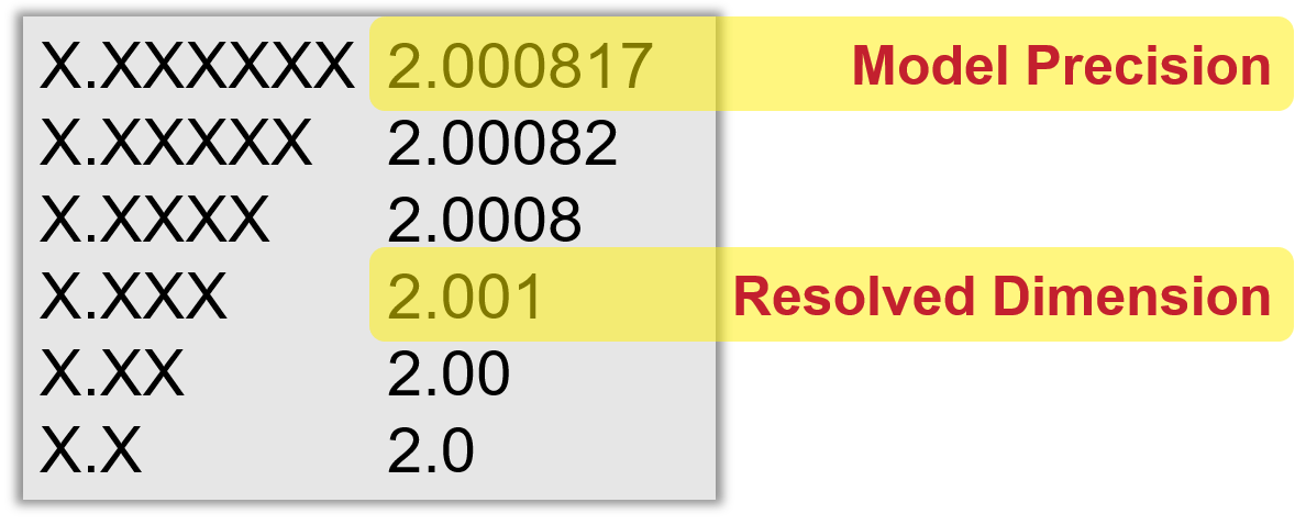 |
| Term: Simplified Drawing | |
| Definition: A drawing with minimal views and dimensional characteristics that relies on the model to provide complete part definition. |
| Term: Supplemental Geometry | |
| Definition: Geometric elements included in product definition data to communicate design requirements but not intended to represent an item. | 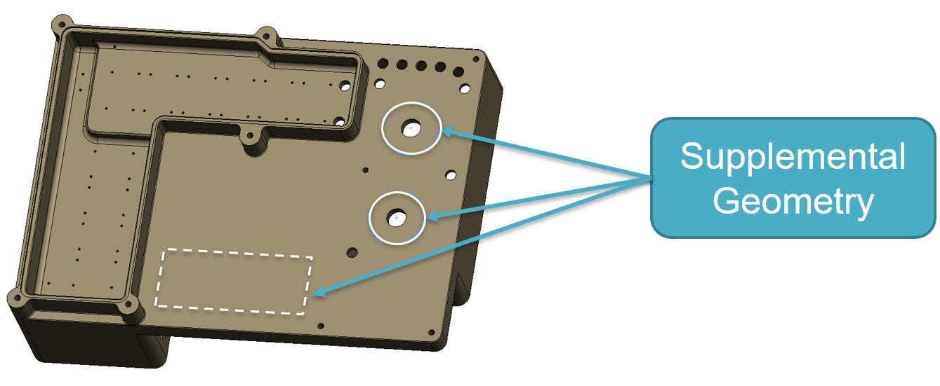 |